background image

2 2

BIOS SETUP UTILITY

Main

Advanced

H/W Monitor

Boot

Security

Exit

System Overview

System Time

System Date

[

:00:09]

[Thu 07/29/2004]

Use [Enter], [TAB]
or [SHIFT-TAB] to
select a field.

Use [+] or [-] to
configure system Time.

Select Screen
Select Item

+-

Change Field

Tab

Select Field

F1

General Help

F9

Load Defaults

F10

Save and Exit

ESC

Exit

BIOS Version
Processor Type
Processor Speed
L1 Cache Size
L2 Cache Size

Total Memory

DDR 1
DDR 2

: K8Upgrade-760GX BIOS P1.0
: AMD Athlon(tm) 64 Processor 3400+
: 2200 MHz
: 128KB
: 1024KB

: 256MB with 64MB shared memory
: 256MB/166MHz (DDR333)
: None

v02.54 (C) Copyright 1985-2003, American Megatrends, Inc.

17

3.1.2 Navigation Keys

Please check the following table for the function description of each navigation

key.

Navigation Key(s)

Function Description

       /

Moves cursor left or right to select Screens

       /

Moves cursor up or down to select items

   +  /  -

To change option for the selected items

<Enter>

To bring up the selected screen

<F1>

To display the General Help Screen

<F9>

To load optimal default values for all the settings

<F10>

To save changes and exit the BIOS SETUP UTILITY

<ESC>

To jump to the Exit Screen or exit the current screen

3.2

Main Screen

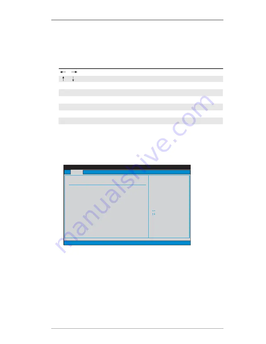
When you enter the BIOS SETUP UTILITY, the Main screen will appear and display

the system overview.

System Time [Hour:Minute:Second]

Use this item to specify the system time.

System Date [Day Month/Date/Year]

Use this item to specify the system date.

Summary of Contents for K8UPGRADE-760GX

Page 1: ...1 MOTHERBOARD K8Upgrade 760GX User Manual Version 1 0 Published August 2004 Copyright 2004 ASRock INC All rights reserved...

Page 2: ...missions that may appear in this manual With respect to the contents of this manual ASRock does not provide warranty of any kind either expressed or implied including but not limited to the implied wa...

Page 3: ...nstallation 19 2 8 Hot Plug Function for SATA HDDs 19 2 9 Making An SATA Driver Diskette 20 3 BIOS SETUP UTILITY 21 3 1 Introduction 21 3 1 1 BIOS Menu Bar 21 3 1 2 Navigation Keys 22 3 2 Main Screen...

Page 4: ...4 Software Support 37 4 1 Install Operating System 37 4 2 Support CD Information 37 4 2 1 Running Support CD 37 4 2 2 Drivers Menu 37 4 2 3 Utilities Menu 37 APPENDIX AMD s Cool n QuietTM Technology 3...

Page 5: ...ed the content of this manual will be subject to change without notice In case any modifications of this manual occur the updated version will be available on ASRock website without further notice You...

Page 6: ...ata Transfer Rate Floppy Port Supports up to 2 Floppy Disk Drives Audio 5 1 channels AC 97 Audio OnBoard VGA Mirage 2 GPU supports DirectX 8 1 LAN Speed 802 3u 10 100 Ethernet Supports Wake On LAN Har...

Page 7: ...is detected the system will automatically shutdown Before you resume the system please check if the CPU fan on the motherboard functions properly and unplug the power cord then plug it back again To i...

Page 8: ...Controller 33 Internal Audio Connector CD1 Black 16 Primary Serial ATA Connector SATA1 34 Shared USB 2 0 Header USB45 Blue 17 Secondary Serial ATA Connector SATA2 35 J1 J8 Jumpers 18 System Panel Head...

Page 9: ...Port 7 USB 2 0 Ports USB01 2 RJ 45 Port 8 USB 2 0 Ports USB23 3 Line In Light Blue 9 VGA Port 4 Line Out Lime 10 PS 2 Keyboard Port Purple 5 Microphone Pink 11 PS 2 Mouse Port Green 6 Shared USB 2 0 P...

Page 10: ...cause severe damage to the motherboard peripherals and or components 1 Unplug the power cord from the wall socket before touching any component 2 To avoid damaging the motherboard components due to s...

Page 11: ...tab to indicate that it is locked 2 2 Installation of CPU Fan and Heatsink After you install the CPU into this motherboard it is necessary to install a larger heatsink and cooling fan to dissipate he...

Page 12: ...k a DIMM slot by pressing the retaining clips outward Step 2 Align a DIMM on the slot such that the notch on the DIMM matches the break on the slot The DIMM only fits in one correct orientation It wil...

Page 13: ...ase refer to the table below for the correct jumper settings This yellow colored Future CPU Port is not an AGP slot Please do NOT insert any AGP card into it NOTE When adjusting the jumper settings yo...

Page 14: ...ith v 92 Modem functionality Installing an expansion card Step 1 Before installing the expansion card please make sure that the power supply is switched off or the power cord is unplugged Please read...

Page 15: ...the front panel and the rear panel audio connectors can work Clear CMOS Jumper CLRCMOS2 see p 8 No 23 Note CLRCMOS2 allows you to clear the data in CMOS The data in CMOS includes system setup informa...

Page 16: ...er to the instruction of your IDE device vendor for the details Besides to optimize compatibility and performance please connect your hard disk drive to the primary IDE connector IDE1 blue and CD ROM...

Page 17: ...B ports 4 5 on ASRock I O PlusTM will not be able to function Infrared Module Header This header supports an 5 pin IR1 optional wireless transmitting see p 8 No 9 and receiving infrared module Interna...

Page 18: ...connector and see p 8 No 3 match the black wire to the ground pin ATX Power Connector Please connect an ATX power 20 pinATXPWR1 supply to this connector see p 8 No 11 COM Port Header This COM port hea...

Page 19: ...herboard supports Hot Plug function for SATA devices What is Hot Plug Function If the SATA HDDs are NOT set for RAID configuration it is called Hot Plug for the action to insert and remove the SATA HD...

Page 20: ...ss Y STEP5 The system will start to format the floppy diskette and copy SATA drivers into the floppy diskette Once you have the SATA driver diskette ready you may start to install Windows 2000 Windows...

Page 21: ...tart by turning the system off and then back on Because the BIOS software is constantly being updated the following BIOS setup screens and descriptions are for reference purpose only and they may not...

Page 22: ...n Megatrends Inc 17 3 1 2 Navigation Keys Please check the following table for the function description of each navigation key Navigation Key s Function Description Moves cursor left or right to selec...

Page 23: ...ollowing items CPU Configuration Chipset Configuration ACPI Configuration IDE Configuration PCIPnP Configuration Floppy Configuration SuperIO Configuration and USB Configuration Setting wrong values i...

Page 24: ...ESC Exit v02 54 C Copyright 1985 2003 American Megatrends Inc Advanced Select Screen Select Item Change Option F1 General Help F9 Load Defaults F10 Save and Exit ESC Exit Actual Frequency MHz CPU Hos...

Page 25: ...lt value of this option is Disabled It will allow better tolerance for memory compatibility when it is set to Enabled Bank Interleaving Interleaving allows memory accesses to be spread out over banks...

Page 26: ...used for graphics memory It is recommended to leave this field at the default value unless the installed AGP card s specifications requires other sizes AGP Data Rate For an AGP 3 0 card you may set A...

Page 27: ...s installed into the FUTURE_CPU_PORT on this motherboard you may set the HyperTransport width as 8 bit or Auto The default value is Auto HT Speed For both 754 Pin CPU and 939 Pin CPU if ASRock 939CPU...

Page 28: ...er On Use this item to enable or disable PCI devices to turn on the system from the power soft off mode PS 2 Keyboard Power On Use this item to enable or disable PS 2 keyboard to turn on the system fr...

Page 29: ...tect the hard disk drive After selecting the hard disk information into BIOS use a disk utility such as FDISK to partition and format the new IDE hard disk drives This is necessary so that you can wri...

Page 30: ...T Use this item to enable or disable the S M A R T Self Monitoring Analysis and Reporting Technology feature Configuration options Disabled Auto Enabled 32 Bit Data Transfer Use this item to enable 3...

Page 31: ...py Controller Serial Port Address Infrared Port Address Parallel Port Address Parallel Port Mode EPP Version ECP Mode DMA Channel Parallel Port IRQ OnBoard Game Port OnBoard MIDI Port Enabled 3F8 IRQ4...

Page 32: ...onfiguration options Normal Bi Directional and ECP EPP EPP Version Use this item to set the EPP version Configuration options 1 9 and 1 7 ECP Mode DMA Channel Use this item to set the ECP mode DMA cha...

Page 33: ...C 98 F 2833 RPM N A 1 532 V 3 129 V 4 877 V 11 741 V 31 C 87 F Main Advanced Boot Security Exit H W Monitor 3 3 8 USB Configuration USB Controller Use this item to enable or disable the use of USB con...

Page 34: ...nable or disable the boot from network feature Select Screen Select Item Change Option F1 General Help F9 Load Defaults F10 Save and Exit ESC Exit v02 54 C Copyright 1985 2003 American Megatrends Inc...

Page 35: ...the available devices in your system Likewise you may also specify the boot sequence from the available devices for the hard disk drives the removable drives and the CD DVD drives 3 6 Security Screen...

Page 36: ...ct this option it will pop out the following message Save configuration changes and exit setup Select OK to save the changes and exit the BIOS SETUP UTILITY Discard Changes and Exit When you select th...

Page 37: ...n using the support CD insert the CD into your CD ROM drive The CD automatically displays the Main Menu if AUTORUN is enabled in your computer If the Main Menu did not appear automatically locate and...

Page 38: ...creen Saver tab 4 Click the Power button The following dialog box appears 5 From the Power schemes combo list box select Minimal Power Management 6 Click OK to implement settings If you are using Wind...

Reviews: