ASROCK K8A8X-M User Manual Download Page 8

8

88

88

1.3

1.3

1.3

1.3

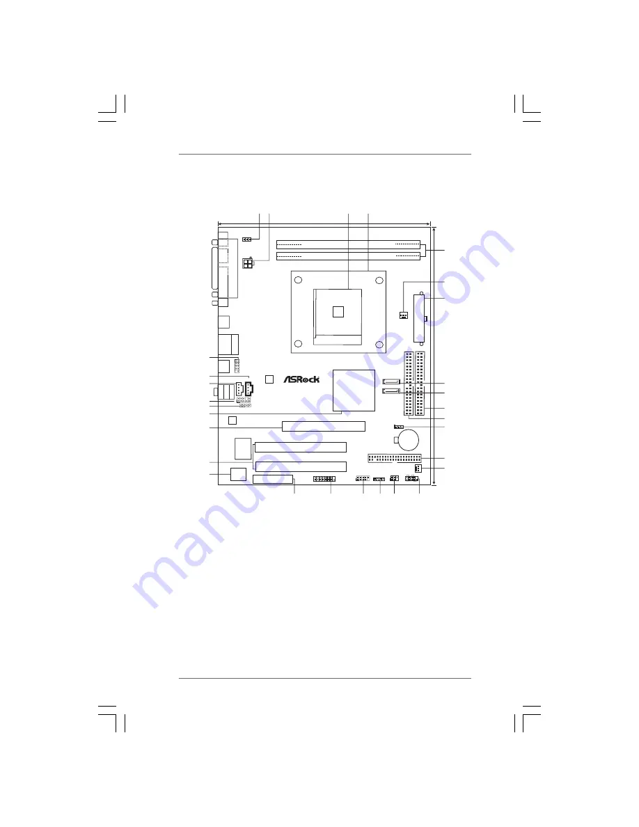
1.3 Motherboard Layout

Motherboard Layout

Motherboard Layout

Motherboard Layout

Motherboard Layout

 1

PS2_USB_PWR1  Jumper

16

Infrared  Module  Header  (IR1)

 2

ATX  12V  Connector  (ATX12V1)

17

Chassis  Speaker  Header  (SPEAKER 1)

 3

CPU  Socket

18

USB 2.0  Header  (USB67, Blue)

 4

CPU  Heatsink  Retention  Module

19

Game  Port  Header  (GAME1)

 5

2 x 184-pin  DDR  DIMM  Slots  (DDR1- 2)

20

AMR  Slot  (AMR1)

 6

CPU  Fan  Connector  (CPU_FAN1)

21

Flash  Memory

 7

ATX  Power  Connector  (ATXPWR1)

22

2 x PCI  Slots  (PCI1, PCI2)

 8

Secondary  Serial  ATA  Connector  (SATA2)

23

AGP  Slot  (1.5V_AGP1)

 9

Primary  Serial  ATA  Connector  (SATA1)

24

Bridge  Controller

10

Primary  IDE  Connector  (IDE1, Blue)

25

JR1 Jumper / JL1  Jumper

11

Secondary  IDE  Connector  (IDE2, Black)

26

Front  Panel  Audio  Header  (AUDIO1)

12

Clear  CMOS  Jumper  (CLRTC1)

27

Internal  Audio  Connector: AUX1  (White)

13

Floppy  Connector  (FLOPPY1)

28

Internal  Audio  Connector: CD1 (Black)

14

Chassis  Fan  Connector  (CHA_FAN1)

29

Shared USB 2.0  Header  (USB45, Blue)

15

System  Panel  Header  (PANEL1)

DDR2 (64/72 bit, 184-pin module)

DDR1 (64/72 bit, 184-pin module)

A

T

XPWR1

IDE2 IDE1

SATA2

SATA1

SOCKET754

ALi

M1689

Chipset

1.5V_AGP1

CMOS

Battery

CLRTC1

CHA_FAN1

USB67

1

SPEAKER1

1

IR1

1

HDLED

RESET

PLED PWRBTN

1

PANEL 1

FLOPPY1

CPU_FAN1

PS2_USB_PWR1

1

Shared
USB 2.0
T: USB4
B: USB5

1

USB4_5

PCI 1

PCI 2

AMR1

2MB

BIOS

Super

I/O

AUDIO

CODEC

1

AUDIO1

JR1 JL1

CD1

AUX1

LAN
PHY

T

op:

Line

In

Center:

Line

Out

Bottom:

Mic

In

USB 2.0
T: USB0
B: USB1

Top:
RJ-45

USB 2.0
T: USB2
B: USB3

P

ARALLEL

P

ORT

COM1

PS2

Mouse

PS2

Keyboard

24.4cm

(9.6-in)

19.8cm (7.8-in)

AGP 8X

FSB800

SATA

K8A8X-M

ATA133

DDR400

USB2.0

5.1CH

ATX12V1

GAME1

1

1 2

4

3

5

6

7

8

10

12

13
14

11

9

15

20

21

19

16

18 17

29

28

25

26

24

22

23

27

1

Summary of Contents for K8A8X-M

Page 1: ...1 1 1 1 1 K8A8X M User Manual Version 1 0 Published April 2005 Copyright 2005 ASRock INC All rights reserved...

Page 2: ...ASRock ASRock assumes no responsibility for any errors or omissions that may appear in this manual With respect to the contents of this manual ASRock does not provide warranty of any kind either expr...

Page 3: ...SATA Hard Disks Installation 18 2 8 Making a SATA Driver Diskette For SATA Operation in RAID Mode 19 2 9 SATA Operating in non RAID Mode 19 3 3 3 3 3 BIOS S BIOS S BIOS S BIOS S BIOS SETUP UTILITY ETU...

Page 4: ...Support CD Information 36 4 2 1 Running Support CD 36 4 2 2 Drivers Menu 36 4 2 3 Utilities Menu 36 4 2 4 Contact Information 36 APPENDIX AMD s Cool n Quiet APPENDIX AMD s Cool n Quiet APPENDIX AMD s...

Page 5: ...BIOS software might be updated the content of this manual will be subject to change without notice In case any modifications of this manual occur the updated version will be available on ASRock websit...

Page 6: ...to 2 floppy disk drives Audio 5 1 channels AC 97 Audio LAN Speed 802 3u 10 100 Ethernet supports Wake On LAN Hardware Monitor CPU temperature sensing Motherboard temperature sensing CPU overheat shut...

Page 7: ...g the power cord then plug it back again To improve heat dissipation remember to spray thermal grease between the CPU and the heatsink when you install the PC system 2 Do NOT use a 3 3V AGP card on th...

Page 8: ...Header AUDIO1 12 Clear CMOS Jumper CLRTC1 27 Internal Audio Connector AUX1 White 13 Floppy Connector FLOPPY1 28 Internal Audio Connector CD1 Black 14 Chassis Fan Connector CHA_FAN1 29 Shared USB 2 0...

Page 9: ...I O PlusTM TM TM TM TM 1 Parallel Port 7 2 x USB 2 0 Ports USB0 USB1 2 RJ 45 Port 8 2 x USB 2 0 Ports USB2 USB3 3 Line In Light Blue 9 Serial Port COM1 4 Line Out Lime 10 PS 2 Keyboard Port Purple 5 M...

Page 10: ...ower is switched off or the power cord is detached from the power supply Failure to do so may cause severe damage to the motherboard peripherals and or components 1 Unplug the power cord from the wall...

Page 11: ...2 2 2 Installation of CPU Fan and Heatsink Installation of CPU Fan and Heatsink Installation of CPU Fan and Heatsink Installation of CPU Fan and Heatsink Installation of CPU Fan and Heatsink After you...

Page 12: ...connect power supply before adding or removing DIMMs or the system components Step 1 Unlock a DIMM slot by pressing the retaining clips outward Step 2 Align a DIMM on the slot such that the notch on t...

Page 13: ...n of your AGP card please check with the AGP card vendors Installing an expansion card Installing an expansion card Installing an expansion card Installing an expansion card Installing an expansion ca...

Page 14: ...higher standby current provided by power supply JR1 JL1 Jumpers see p 8 No 25 Note If JR1 and JL1 Jumpers are short both the front panel and the rear panel audio connectors can work Clear CMOS CLRTC1...

Page 15: ...is plugged into Pin1 side of the connector Primary IDE Connector Blue Secondary IDE Connector Black 39 pin IDE1 see p 8 No 10 39 pin IDE2 see p 8 No 11 Note If you use only one IDE device on this mot...

Page 16: ..._5 the USB ports 4 5 on ASRock I O PlusTM will not be able to function Infrared Module Header This header supports an optional 5 pin IR1 wireless transmitting and see p 8 No 16 receiving infrared modu...

Page 17: ...Fan Connector Please connect the CPU fan 3 pin CPU_FAN1 cable to this connector and see p 8 No 6 match the black wire to the ground pin Game Connector Connect a Game cable to this 15 pin GAME1 connec...

Page 18: ...the SATA hard disks STEP1 Install the SATA hard disks into the drive bays of your chassis STEP2 Connect the SATA power cable to the SATA hard disk STEP3 Connect one end of the SATA data cable to the m...

Page 19: ...copy files YN Please insert a floppy diskette into the floppy drive and press Y STEP5 The system will start to format the floppy diskette and copy SATA drivers into the floppy diskette 2 9 2 9 2 9 2...

Page 20: ...button on the system chassis You may also restart by turning the system off and then back on Because the BIOS software is constantly being updated the following BIOS setup screens and descriptions are...

Page 21: ...3 2 3 2 3 2 Main Screen Main Screen Main Screen Main Screen Main Screen When you enter the BIOS SETUP UTILITY the Main screen will appear and display the system overview System Time Hour Minute Second...

Page 22: ...y cause system to malfunction Options for CPU Select Screen Select Item Enter Go to Sub Screen F1 General Help F9 Load Defaults F10 Save and Exit ESC Exit v02 54 C Copyright 1985 2003 American Megatre...

Page 23: ...lts F10 Save and Exit ESC Exit Actual Frequency MHz CPU Host Frequency 200 Auto Spread Spectrum Cool n Quiet Disabled Enabled Processor Maximum Multiplier Processor Maximum Voltage Processor Multiplie...

Page 24: ...using Auto You can set one of the standard values as listed 133 MHz DDR266 166 MHz DDR333 200 MHz DDR400 Flexibility Option The default value of this option is Disabled It will allow better tolerance...

Page 25: ...lt value is 4X AGP Fast Write Use this item to enable or disable the feature of AGP fast write protocol support Primary Graphics Adapter This item will switch the PCI Bus scanning order while searchin...

Page 26: ...n the power recovers Ring In Power On Use this item to enable or disable Ring In signals to turn on the system from the power soft off mode PCI Devices Power On Use this item to enable or disable PCI...

Page 27: ...54 C Copyright 1985 2003 American Megatrends Inc OnBoard IDE Controller OnBoard SATA Controller SATA Operation Mode Primary IDE Master Primary IDE Slave Secondary IDE Master Secondary IDE Slave Both...

Page 28: ...Device such as MO LBA Large Mode Use this item to select the LBA Large mode for a hard disk 512 MB under DOS and Windows for Netware and UNIX user select Disabled to disable the LBA Large mode Block...

Page 29: ...installed PCI expansion cards specifications require other settings PCI IDE BusMaster Use this item to enable or disable the PCI IDE BusMaster feature Advanced PCI PnP Settings Value in units of PCI...

Page 30: ...ard infrared port or disable it Configuration options Disabled 2F8 IRQ3 and 2E8 IRQ3 BIOS SETUP UTILITY Floppy Configuration Select the type of floppy drive connected to the system Select Screen Selec...

Page 31: ...Version Configuration options Normal Bi Directional and ECP EPP EPP Version Use this item to set the EPP version Configuration options 1 9 and 1 7 ECP Mode DMA Channel Use this item to set the ECP mod...

Page 32: ...t Monitoring Screen Hardware Health Event Monitoring Screen In this section it allows you to monitor the status of the hardware on your system including the parameters of the CPU temperature motherboa...

Page 33: ...um Lock If this item is set to On it will automatically activate the Numeric Lock function after boot up Boot Settings Configure Settings during System Boot Select Screen Select Item Enter Go to Sub S...

Page 34: ...d you may also clear it BIOS SETUP UTILITY Boot Device Priority Specifies the boot sequence from the available devices A device enclosed in parenthesis has been disabled in the corresponding type menu...

Page 35: ...ng any changes Discard Changes When you select this option it will pop out the following message Discard changes Select OK to discard all changes Load Optimal Defaults When you select this option it w...

Page 36: ...pport CD insert the CD into your CD ROM drive The CD automatically displays the Main Menu if AUTORUN is enabled in your computer If the Main Menu did not appear automatically locate and double click o...

Page 37: ...View for Windows XP only 3 Double click the Display icon in the Control Panel then select the Screen Saver tab 4 Click the Power button The following dialog box appears 5 From the Power schemes combo...

Reviews: