background image

38

English

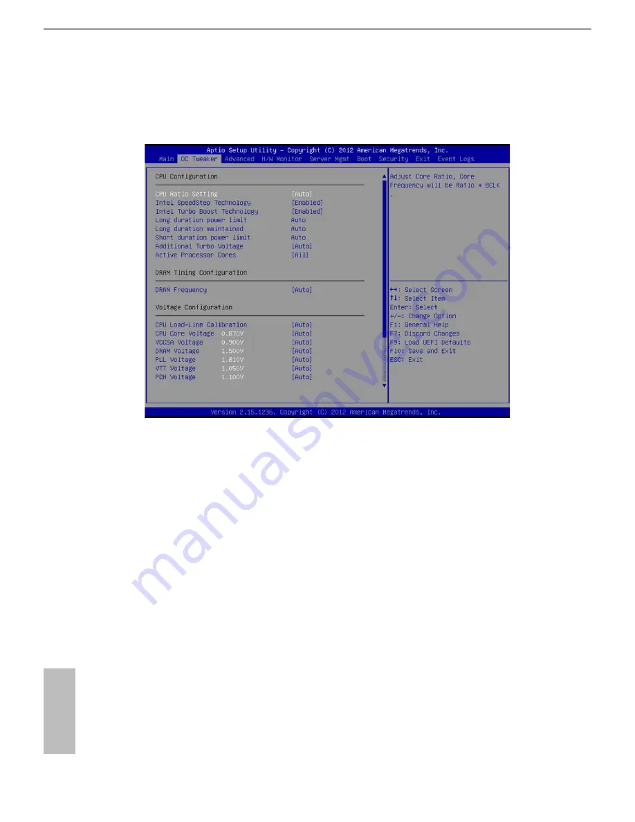
3.3  OC Tweaker Screen

In the OC Tweaker screen, you can set up overclocking features.

3.3.1  CPU Coniguration

CPU Ratio Setting

Use this item to adjust the Core Ratio. he CPU speed is determined by the CPU 

Ratio multiplied with the BCLK. Increasing the CPU Ratio will increase the internal 

CPU clock speed without afecting the clock speed of other components.  

Max Ratio

When the CPU Ratio Setting is set to [All Core], use this item to set the maximum 

core ratio for all cores. he valid value ranges diferently according to your CPU 

model.

x-Core Ratio Limit

 (x means number)

When the CPU Ratio Setting is set to [Per Core], use this item to set the CPU core 

ratio individaully. he valid value ranges diferently according to your CPU model. 

(Supported only for overclocking CPU models)

Summary of Contents for EPC602D8A

Page 1: ......

Page 2: ...implied including but not limited to the implied warranties or conditions of merchantability or itness for a particular purpose In no event shall ASRock Rack its directors oicers employees or agents...

Page 3: ...ant to know more about ASRock Rack you re welcome to visit ASRock Rack s website at www ASRockRack com or you may contact your dealer for further information ASRock Rack Incorporation 6F No 37 Sec 2 J...

Page 4: ...nstallation Precautions 15 2 3 Installing the CPU 16 2 4 Installing the CPU Fan and Heatsink 19 2 5 Installation of Memory Modules DIMM 20 2 6 Expansion Slots PCI and PCI Express Slots 22 2 7 Jumper S...

Page 5: ...LT SX Coniguration 44 3 4 4 WHEA Coniguration 45 3 4 5 CPU Coniguration 46 3 4 6 North Bridge Coniguration 48 3 4 7 South Bridge Coniguration 51 3 4 8 USB Coniguration 53 3 4 9 ME Subsystem 54 3 4 10...

Page 6: ...ll Operating System 72 4 2 Support CD Information 72 4 2 1 Running The Support CD 72 4 2 2 Drivers Menu 72 4 2 3 Utilities Menu 72 4 2 4 Contact Information 72 Chapter 5 Troubleshooting 73 5 1 Trouble...

Page 7: ...602D8A V Motherboard ATX Form Factor 12 0 in x 9 6 in 30 5 cm x 24 4 cm Support CD User Manual 4 x SATA3 cables 50cm 2 x SATA3 cables 60cm 1 x I O Shield If any items are missing or appear damaged con...

Page 8: ...pansion Slot Slot 1 is the closest to the CPU Slot 1 x8 Slot 2 x16 x16 x0 or x8 x8 with Slot 1 Slot 3 x8 Slot 4 x16 x16 x0 or x8 x8 with Slot 3 Slot 5 x8 slot with EE x8 x0 or x4 x4 with Slot 6 Slot 6...

Page 9: ...DR3 16MB Output Supports D Sub with max resolution up to 1920x1200 60Hz Audio Audio code 7 1 CH HD Audio with Content Protection Realtek ALC892 Audio Codec To conigure 7 1 CH HD Audio it is required t...

Page 10: ...anel 1 SPDIF Header 1 1394 Header 1 Front Panel 1 Speaker 1 Dr Debug with LED 1 System BIOS BIOS Type 64Mb AMI UEFI Legal BIOS BIOS Features Plug and Play PnP ACPI 1 1 Compliance Wake Up Events SMBIOS...

Page 11: ...Temperature Operation temperature 10 C 35 C Non operation temperature 40 C 70 C his motherboard supports Wake from on Board LAN To use this function please make sure that the Wake on Magic Packet fro...

Page 12: ...y you can press the F6 key during the POST or the F2 key to enter into the BIOS setup menu to access ASRock Rack Instant Flash Just launch this tool and save the new BIOS ile to your USB lash drive lo...

Page 13: ...odule ATX12V1 Top LINE IN Center FRONT Bottom MIC IN AUDIO1 USB 2 0 T USB_2 B USB_1 PCIE6 PCIE5 PCIE3 PCIE1 PCIE2 PCIE4 1 PSU_SMB1 FRNT_FAN1 Dr Debug SATA_SGPIO1 1 SATA_SGPIO2 1 SATA_1 TPM1 1 USB_5 US...

Page 14: ...ter FRONT Bottom MIC IN AUDIO1 USB 2 0 T USB_2 B USB_1 PCIE6 PCIE5 PCIE3 PCIE1 PCIE2 PCIE4 1 PSU_SMB1 FRNT_FAN1 Dr Debug SATA_SGPIO1 1 SATA_SGPIO2 1 SATA_1 TPM1 1 USB_5 USB_3_4 1 PANEL1 1 1394_2 1 COM...

Page 15: ...onnector FRONT_FAN2 13 Auxiliary Panel Header AUX_PANEL1 14 SATA SGPIO Connector SATA_SGPIO1 15 SATA SGPIO Connector SATA_SGPIO2 16 SATA2 Connector SATA_4 Blue 17 SATA3 Connector SATA_M0 White 18 SATA...

Page 16: ..._SMB_1 35 IEEE 1394 Header 1394_2 36 COM Port Header COM2 37 Intelligent Platform Management Bus header IPMB_1 38 Vertical Type A USB 2 0 USB_5 39 ME Recovery Jumper ME_RECOVERY1 40 HDMI_SPDIF Header...

Page 17: ...N2 9 Line In Light Blue 4 LAN RJ 45 Port LAN1 10 Front Speaker Lime 5 LAN RJ 45 Port IPMI_LAN 11 Microphone Pink 6 USB 3 0 Ports USB3_1 2 EPC602D8A V No Description No Description 1 Serial Port COM1 6...

Page 18: ...inking Data Activity Orange 100Mbps connection On 100Mbps connection Green 1Gbps connection here are two LEDs on each LAN port Please refer to the table below for the LAN port LED indications LAN Port...

Page 19: ...CIEx2 Slot7 PCI E GEN2 x8 Slot EE x2 PCIEx16 Slot1 PCI E GEN3 x8 Slot EE x0 x8 with Slot2 Slot2 PCI E GEN3 x16 Slot EE x16 x8 with Slot1 Slot3 PCI E GEN3 x8 Slot EE x0 x8 with Slot4 Slot4 PCI E GEN3 x...

Page 20: ...Super I O Intel C602 Remove the standoff from the chassis Make sure to unplug the power cord before installing or removing the motherboard Failure to do so may cause physical injuries to you and dama...

Page 21: ...the wall socket before touching any components 2 To avoid damaging the motherboard s components due to static electricity NEVER place your motherboard directly on the carpet or the like Also remember...

Page 22: ...16 English 2 3 Installing the CPU A B A B 1 2 3...

Page 23: ...EPC602D8A EPC602D8A V 17 English B A 4 5 6...

Page 24: ...18 English he cover must be placed if returning the motherboard for ater service A B A B 7 8 9 B C A...

Page 25: ...P U _ F A N 1 2 CPU fan for narrow ILM socket Support an active or passive heatsink 1 Before you installed the heatsink you need to spray thermal interface material between the CPU and the heatsink to...

Page 26: ...d 2 Populated Populated Populated Populated 1 For dual channel coniguration you always need to install identical the same brand speed size and chip type DDR3 DIMM pairs 2 It is unable to activate Dual...

Page 27: ...EPC602D8A EPC602D8A V 21 English 1 2 3...

Page 28: ...and PCIE4 PCIE 3 0 x16 slot from CPU are used for PCI Express x16 lane width graphics cards Slot Generation Mechnical Eletrical Source PCIE 1 3 0 x8 x8 CPU PCIE 2 3 0 x16 x16 CPU PCIE 3 3 0 x8 x8 CPU...

Page 29: ...necessary hardware settings for the card before you start the installation Step 2 Remove the system unit cover if your motherboard is already installed in a chassis Step 3 Remove the bracket facing th...

Page 30: ...p is placed on the pins the jumper is Short If no jumper cap is placed on the pins the jumper is Open he illustration shows a 3 pin jumper whose pin1 and pin2 are Short when a jumper cap is placed on...

Page 31: ...ower LED Connect to the power status indicator on the chassis front panel he LED is on when the system is operating he LED keeps blinking when the system is in S1 S3 sleep state he LED is of when the...

Page 32: ...tween peripheral equipment in the system which has slower transmission rates and power management equipment B Internet status indicator 2 pin LAN1_LED LAN2_LED hese two 2 pin headers allow you to use...

Page 33: ...D P P USB_PWR P P USB_PWR 1 Besides two USB 2 0 ports on the I O panel there is one header on this motherboard Each USB 2 0 header can support two ports USB 2 0 Connector USB_5 see p 7 No 38 USB 3 0 H...

Page 34: ...output to HDMI VGA card allows the system to connect HDMI Digital TV projector LCD devices Please connect the HDMI connector of HDMI VGA card to this header 1 High Deinition Audio supports Jack Sensi...

Page 35: ...lease connect fan cables to the fan connectors and match the black wire to the ground pin All fans support Fan Control ATX Power Connector 24 pin ATXPWR1 see p 7 No 8 his motherboard provides a 24 pin...

Page 36: ...gital certiicates passwords and data A TPM system also helps enhance network security protects digital identities and ensures platform integrity Serial General Purpose Input Output Headers 7 pin SATA_...

Page 37: ...1 GND Please connect the thermal sensor cable to either pin 1 2 or pin 2 3 and the other end to the device which you wish to monitor its temperature Baseboard Management Controller SMBus Headers 5 pin...

Page 38: ...CI E devices or try installing them in other slots If the problem still exists please remove all PCI E devices or try using another VGA card A0 A7 Problem related to IDE or SATA devices Please re inst...

Page 39: ...system please insert the support CD to your optical drive irst hen the drivers compatible to your system can be auto detected and listed on the support CD driver page Please follow the order from top...

Page 40: ...r handles all non TCP IP traic he Secondary adapter will receive fallback traic if the primary fails If the Preferred Primary adapter fails but is later restored to an active status control is automat...

Page 41: ...has a menu bar with the following selections Item Description Main To set up the system time date information OC Tweaker To set up overclocking features Advanced To set up the advanced UEFI features...

Page 42: ...selected items Tab Switch to next function Enter To bring up the selected screen PGUP Go to the previous page PGDN Go to the next page HOME Go to the top of the screen END Go to the bottom of the scre...

Page 43: ...7 English 3 2 Main Screen Once you enter the UEFI SETUP UTILITY the Main screen will appear and display the system overview he Main screen provides system overview information and allows you to set th...

Page 44: ...nternal CPU clock speed without afecting the clock speed of other components Max Ratio When the CPU Ratio Setting is set to All Core use this item to set the maximum core ratio for all cores he valid...

Page 45: ...will be lowered ater a period of time A lower limit can protect the CPU and save power while a higher limit may improve performance Long Duration Maintained Use this item to conigure time window which...

Page 46: ...age Use this to select PLL Voltage he default value is Auto VTT Voltage Use this to select VTT Voltage he default value is Auto PCH Voltage Use this to conigure PCH Voltage he default value is Auto 3...

Page 47: ...gurations for the following items Easy RAID Install er ACPI Configuration Intel TXT LS SX Configuration WHEA Configuration CPU Coniguration North Bridge Coniguration South Bridge Coniguration USB Coni...

Page 48: ...asy RAID Installer can help you to copy the RAID driver from a support CD to your USB storage device Ater copying the RAID driver to your USB storage device please change SATA Mode to RAID then you ca...

Page 49: ...l enable this feature if the OS supports it ACPI HPET Table Use this item to enable or disable ACPI HPET Table he default value is Enabled Please set this option to Enabled if you plan to use this mot...

Page 50: ...sable USB Keyboard Remote to turn on the system from the power sot of mode USB Mouse Power On Use this item to enable or disable USB Mouse to turn on the system from the power sot of mode 3 4 3 Intel...

Page 51: ...EPC602D8A EPC602D8A V 45 English 3 4 4 WHEA Coniguration WHEA Support Use this option to enable or disable Windows Hardware Error Architecture he default value is Enabled...

Page 52: ...ded sotware is improved Active Processor Cores Select the number of cores to enable in each processor package Limit CPUID Maxinum This function allows you to limit CPUID maximum value It is set as Dis...

Page 53: ...ation Technology Intel Virtualization Technology allows a platform to run multiple operating systems and applications in independent partitions so that one computer system can function as multiple vir...

Page 54: ...Graphics Adapter If a PCI Express graphics card is installed on the motherboard you may use this option to select PCI Express or Onboard as the primary graphics adapter Onboard VGA Use this to enable...

Page 55: ...ue is Auto Memory Coniguration Memory Mode Select the mode for memory initialization Independent Independent channel mode Mirroring he memory subsystem writes identical data to two channels simultaneo...

Page 56: ...y interleaving method he default value is Auto Patrol Scrub Patrol Scrub is a background activity initiated by the processor to seek out and ix memory errors he default value is Enabled Demand Scrub F...

Page 57: ...ecovers If Last State is selected the AC power resumes or remains of when the power recovers depending on the last state when an unexpected AC power loss occurs Deep Sleep Mobile platforms support Dee...

Page 58: ...Port LED he default value is Auto Onboard HD Audio Select Enabled Disabled or Auto for the onboard HD Audio feature If you select Enabled the onboard HD Audio will be disabled when PCI Sound Card is...

Page 59: ...cy USB Support Use this option to select legacy support for USB devices There are four configuration options Enabled and Disabled The default value is Enabled Please refer to below descriptions for th...

Page 60: ...54 English 3 4 9 ME Subsystem ME Subsystem screen displays the Intel ME Subsystem Con guration information such as ME Version and ME FW State...

Page 61: ...EPC602D8A EPC602D8A V 55 English 3 4 10 Clock Generator Coniguration Spread Spectrum Use this item to enable or disable the spread spectrum feature he default valu is Disabled...

Page 62: ...es not have these advantages SATA Aggressive Link Power Management Use this item to conigure SATA Aggressive Link Power Management Hard Disk S M A R T Use this item to enable or disable the S M A R T...

Page 63: ...epending on how many SATA ports you have you will see SATA_x x means number listed on the screen with its status indicated as SATA device Model Name or Not Detected Enter either one of the options wil...

Page 64: ...l port Change Settings Use this item to select an optimal setting for Super IO device Serial Port 2 Coniguration Use this item to conigure the onboard serial port 2 Select and enter the Serial Port 2...

Page 65: ...and the host computer to which you are connected exchange information Out of Band Mgmt Management Port Use this item to select the port to be used for out of band management The options include COM1...

Page 66: ...top the data low Once the bufers are empty a start signal can be sent to restart the low Hardware low uses two wires to send start stop signals he options include None Hardware RTS CTS and Sotware Xon...

Page 67: ...s to select CPU Core Voltage he default value is Auto VCCSA Voltage Use this to select VCCSA Voltage he default value is Auto DRAM Voltage Use this to select DRAM Voltage he default value is Auto PLL...

Page 68: ...isk or hard drive and launch this tool then you can update your UEFI only in a few clicks without preparing an additional loppy diskette or other compli cated lash utility Please be noted that the USB...

Page 69: ...fan speed and the critical voltage CPU_FAN 1 his allows you to set the CPU fan 1 s speed he default value is Smart Fan REAR_FAN 1 his allows you to set the rear fan 1 s speed he default value is Smar...

Page 70: ...you to set duty cycle for each stage Smart Fan Temp Control Smart Fan Temp x x means 1 to 11 stage his allows you to set temperature for each stage Watch Dog Timer his allows you to enable or disable...

Page 71: ...amic Unspeciied BMC network parameters is conigured by BMC itself Static Manually enter the IP Address Subnet Mask and Gateway Address in the BIOS for BMC LAN channel coniguration Dynamic IP address S...

Page 72: ...m to set the system boot order Setup Prompt Timeout his shows the number of seconds to wait for setup activation key Bootup Num Lock If this item is set to On it will automatically activate the Numeri...

Page 73: ...sable the feature of Boot Failure Guard Boot Failure Guard Count Use this item to conigure Boot Failure Guard Count Boot From Onboard LAN Use this item to enable or disable the Boot From Onboard LAN f...

Page 74: ...strator account Only the administrator has authority to change the settings in the UEFI Setup Utility Leave it blank and press enter to remove the password User Password Set or change the password for...

Page 75: ...ILITY Discard Changes and Exit When you select this option the following message Discard changes and exit setup will pop out Select Yes to exit the UEFI SETUP UTILITY without saving any changes Discar...

Page 76: ...tions include No Yes Next reset and Yes Every reset If Yes is selected all logged events will be erased When Log is Full Use this item to choose options for reactions to a full Smbios Event Log The op...

Page 77: ...Select to conigure BMC network parameters statically or dynamically by BIOS or BMC Coniguration options Unspeciied Static or Dynamic Unspeciied BMC network parameters are conigured by BMC itself Stati...

Page 78: ...automatically displays the Main Menu if AUTORUN is enabled in your computer If the Main Menu does not appear automatically locate and double click on the ile ASRSetup exe from the root folder in the S...

Page 79: ...t settings 3 Check the settings of the 115V 230V switch on the power supply 4 Verify if the battery on the motherboard provides 3VDC Install a new battery if it does not If there is no video 1 Try rep...

Page 80: ...battery on the motherboard provides 3VDC Install a new battery if it does not 2 Conirm whether your power supply provides adaquate and stable power Other problems 1 Try searching keywords related to y...

Page 81: ...invoice marked with the date of purchase is required By calling your vendor or going to our RMA website http www asrock com support index asp cat RMA you may obtain a Returned Merchandise Authorizatio...

Reviews: