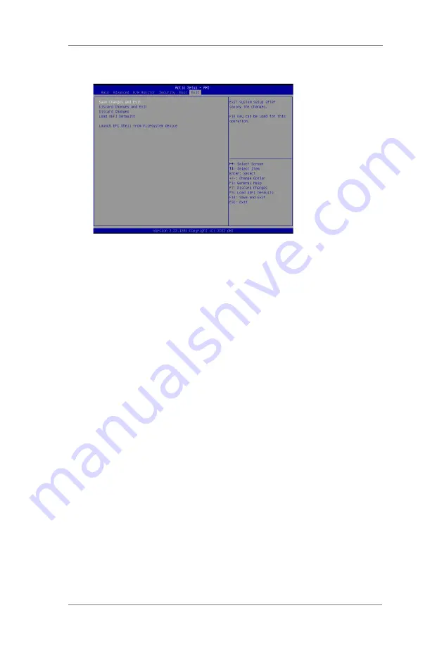
ASRock Industrial IMB-X1231 User Manual Download Page 40

40

3.7  Exit Screen

Save Changes and Exit

When you select this option, it will pop-out the following message, “Save 

configuration changes and exit setup?” Select [OK] to save the changes 

and exit the UEFI SETUP UTILITY.

Discard Changes and Exit

When you select this option, it will pop-out the following message, “Discard 

changes and exit setup?” Select [OK] to exit the UEFI SETUP U

TILITY 

without saving any changes.

Discard Changes

When you select this option, it will pop-out the following message, “Discard 

changes?” Select [OK] to discard all changes.

Load UEFI Defaults 

Load UEFI default values for all the setup questions. F9 key can be used 
for this operation.

Launch EFI Shell from filesystem device

Attempts  to  Launch  EFI  Shell  application  (Shell64.efi)  from  one  of  the 

available filesystem devices.

Summary of Contents for IMB-X1231

Page 1: ...1 IMB X1231 User Manual Version 1 0 Published August 2022 Copyright 2022 ASRockInd INC All rights reserved...

Page 2: ...plied including but not limited to the implied warranties or conditions of merchantability or fitness for a particular purpose In no event shall ASRockInd its directors officers employees or agents be...

Page 3: ...terface and the HDMI logo are trademarks or registered trademarks of HDMI Licensing LLC in the United States and other countries CAUTION RISK OF EXPLOSION IF BATTERY IS REPLACED BY AN INCORRECT TYPE D...

Page 4: ...s 17 2 7 Installation of ROM Socket 22 3 UEFI SETUP UTILITY 23 3 1 Introduction 23 3 1 1 UEFI Menu Bar 23 3 1 2 Navigation Keys 24 3 2 Main Screen 24 3 3 Advanced Screen 25 3 3 1 CPU Configuration 26...

Page 5: ...se the motherboard specifications and the BIOS software might be updated the content of this manual will be subject to change without no tice In case any modifications of this manual occur the updated...

Page 6: ...24 bit up to 1920x1200 60Hz VGA Max resolution up to 1920 x 1200 60Hz MultiDisplay Quad Display Expansion Slot PCIe 1 x PCIe x16 Gen4 Support riser card x8 x8 M 2 1 x M 2 Key E 2230 with PCIe x1 USB...

Page 7: ...A ports Support by special BIOS SATA 4 x SATA3 6Gb s RAID Intel VMD RAID 0 1 5 10 Supported by identical interface PCIe or SATA PCIe interface M 2 Key B M 2 Key M1 2 or 2 M 2 Key M SATA interface SATA...

Page 8: ...8 1 3 Motherboard Layout...

Page 9: ...S Panel Connector 15 Panel Power Select LCD_VCC PNL_PWR1 16 Backlight Power Select LCD_BLT_VCC BKT_PWR1 17 CON_LBKLT_CTL Voltage Level BLT_PWM2 18 Digital Input Output Default Value Setting JGPIO_SET1...

Page 10: ...us Description Status Description Off No Link Off 10Mbps 100Mbps connection Blinking Data Activity Orange 1Gbps connection On Link Green 2 5Gbps connection ACT LINK LED SPEED LED LAN Port This motherb...

Page 11: ...efore you install motherboard components or change any motherboard settings 1 Unplug the power cord from the wall socket before touching any component 2 To avoid damaging the motherboard components du...

Page 12: ...4 Double Data Rate 4 SO DIMM slots 1 The SO DIMM only fits in one correct orientation It will cause permanent damage to the motherboard and the SO DIMM if you force the SO DIMM into the slot at incorr...

Page 13: ...13 1 2 3...

Page 14: ...A 6 7 PERp3 NA 8 9 GND SATA_LED 10 11 PETn3 3 3V 12 13 PETp3 3 3V 14 15 GND 3 3V 16 17 PERn2 3 3V 18 19 PERp2 NA 20 21 GND NA 22 23 PETn2 NA 24 25 PETp2 NA 26 27 GND NA 28 29 PERn1 NA 30 31 PERp1 NA 3...

Page 15: ...15 seconds use a jumper cap to short pin2 and pin3 on CLRMOS1 for 5 seconds However please do not clear the CMOS right after you update the BIOS If you need to clear the CMOS when you just finish upd...

Page 16: ...N_ LBKLT_CTL Note Please set to 1 2 when adjusting brightness by Brightness Control bar under OS Please set to 2 3 when adjusting brightness by BLT_VOL1 DACC1_PCIE_PWR1 PIN1 2 Open No ACC 4 pin DACC1_...

Page 17: ...el see p 8 No 24 functions Chassis Fan Connector Please connect the chassis fan 4 pin CHA_FAN1 cable to the connector and see p 8 No 27 match the black wire to the ground pin Connect the power switch...

Page 18: ...vity LED on the chassis front panel The LED is on when the hard drive is reading or writing data The front panel design may differ by chassis A front panel module mainly consists of power switch reset...

Page 19: ...ard Each USB 2 0 see p 8 No 34 header can support two ports USB 3 2 Gen1 Header There is one header on this 19 pin USB3_4_9 motherboard This USB 3 2 see p 8 No 35 Gen1 header can support two ports J_S...

Page 20: ...A_DATA3 13 LVDS_A_DATA2 14 GND 11 GND 12 LVDS_A_DATA2 9 LVDS_A_DATA1 10 LVDS_A_DATA1 7 LVDS_A_DATA0 8 GND 5 NA 6 LVDS_A_DATA0 3 3 3V 4 NA 1 LCD_VCC 2 LCD_VCC Battery Connector 2 pin BAT1 see p 8 No 36...

Page 21: ...UP PIN Signal Name PIN Signal Name 10 GND 9 JGPIOPWR_R 8 GPP_E6 7 SIO_GP74 6 GPP_E5 5 SIO_GP73 4 GPP_I10 3 SIO_GP72 2 GPP_H23 1 SIO_GP71 ATX Power Input Connector This motherboard provides 24 pin ATXP...

Page 22: ...he actuator cover may be broken The yellow dot Pin1 on the ROM must be installed at pin1 position of the socket white arrow area Make sure the white dot on the ROM is installed outwards of the socket...

Page 23: ...ystem off and then back on Because the UEFI software is constantly being updated the following UEFI setup screens and descriptions are for reference purpose only and they may not exactly match what yo...

Page 24: ...To change option for the selected items Enter To bring up the selected screen F1 To display the General Help Screen F7 Discard changes F9 To load optimal default values for all the settings F10 To sa...

Page 25: ...ol allows you to update system UEFI without entering operating systems first like MS DOS or Windows Just launch this tool and save the new UEFI file to your USB flash drive floppy disk or hard drive t...

Page 26: ...ure can utilize the additional hardware capabilities provided by Vanderpool Technology This option will be hidden if the installed CPU does not support Intel Virtualization Technology Intel SpeedStep...

Page 27: ...Boost Mode Technology Turbo Boost Mode allows processor cores to run faster than marked fre quency in specific conditions The default value is Enabled CPU Thermal Throttling You may select Enabled to...

Page 28: ...lect the bandwidth mode for PCIE1 PCIE1 Link Speed Select the link speed for PCIE1 Share Memory Configure the size of memory that is allocated to the integrated graphics processor when the system boot...

Page 29: ...isable the Onboard LAN2 feature Onboard HD Audio Select Auto Enabled or Disabled for the onboard HD Audio feature If you select Auto the onboard HD Audio will be disabled when PCI Sound Card is plugge...

Page 30: ...pports NCQ and other new features that will improve SATA disk perfor mance but IDE mode does not have these advantages Hybrid Storage Detection and Configuration Mode Use this item to enable or disabl...

Page 31: ...r RS485 COM2 Configuration Use this to set parameters of COM2 Type Select Use this to select COM2 port type RS232 RS422 or RS485 COM3 Configuration Use this to set parameters of COM3 COM4 Configuratio...

Page 32: ...n enable or disable PET Events progress to receive PET events or not The default is Enabled WatchDog Use this to enable or disable AMT WatchDog Timer The default is Dis abled ASF Sensors Table Use thi...

Page 33: ...nabled OCR Windows Recovery Boot Use this to enable or disable One Click Recovery Windows Recovery Boot The default is Enabled OCR Disable Secure Boot Use this to allows CSME to request Secure Boot to...

Page 34: ...he Suspend to RAM feature Select Auto will enable this feature if the OS supports it PCIE Devices Power On Use this item to enable or disable PCIE devices to turn on the system from the power soft off...

Page 35: ...35 3 3 7 USB Configuration USB Power Control Use this option to control USB power M 2 Key_B USB Configuration Enable or disable M 2 Key_B USB Configuration...

Page 36: ...36 3 3 8 Trusted Computing Security Device Support Enable or disable BIOS support for security device...

Page 37: ...fan 1 s speed Configuration options Full On and Automatic Mode The default value is Full On CHA_FAN1 Setting This allows you to set chassis fan 1 s speed Configuration options Full On and Automatic M...

Page 38: ...y the ad ministrator has authority to change the settings in the UEFI Setup Utility Leave it blank and press enter to remove the password User Password Set or change the password for the user account...

Page 39: ...5 0XFFFF means indefinite waiting Bootup Num Lock If this item is set to On it will automatically activate the Numeric Lock function after boot up Full Screen Logo Use this item to enable or disable O...

Page 40: ...ing message Discard changes and exit setup Select OK to exit the UEFI SETUP UTILITY without saving any changes Discard Changes When you select this option it will pop out the following message Discard...

Reviews: