Theta 18 Aerospace Speciality Products Page 9
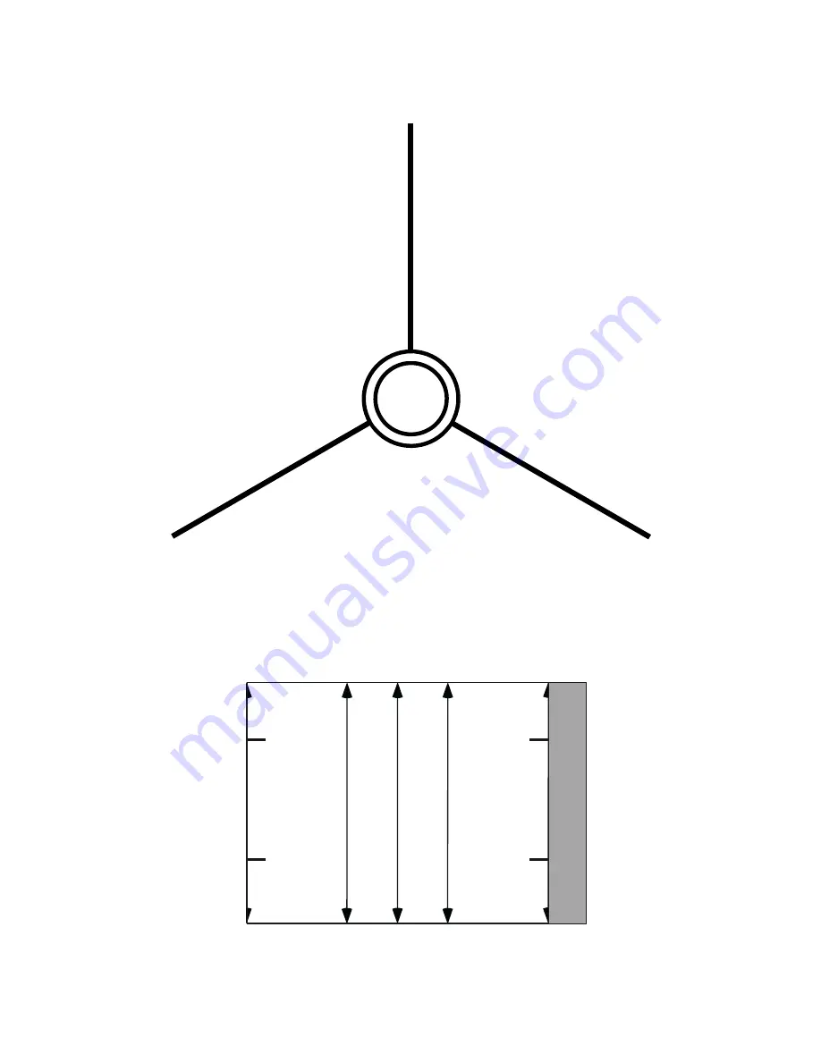
Fin Alignment Guide
L
a
u
n
ch L
g
in
e
Fin Line
TAB
Tube Marking Guide
Page 1: ...ther expressed or implied is made regarding Aerospace Speciality Products products except for replacement or repair at Aerospace Speciality Products option of those products proven to be defective in manufacture within one month from date of original purchase For repair or replacement under this warranty please contact Aerospace Speciality Products Proof of Purchase will be required Note Your stat...
Page 2: ...mer colors as desired clear sanding block tack cloth Assembly Instructions you can use the checkboxes to mark off each step as they are completed 1 We ll start by building the Engine Mount Refer to Figure A as needed Locate the engine tube the red tube the engine block the smaller spiral wound paper block that fits inside the engine tube the 2 centering rings the larger spiral wound rings that fit...
Page 3: ... on each end to align the guide see Figure B Use a piece of tape to hold the guide in place With a sharp pencil mark the body tube at the arrows at the end of each line for the three fins and the launch lug Be sure to note which line is for the launch lug Remove the guide from the tube Using something such as a door frame as shown in Figure C try not to get pencil marks on the door frame while you...
Page 4: ...e G In one smooth motion insert the engine mount into the bottom of the body tube be sure to insert the end with the engine block first The bottom of the lower centering ring should be even with the bottom of the body tube the red engine tube will extend out from the bottom of the body tube as shown in Figure H Wipe away any excess glue that may have come out near the rear centering ring and allow...
Page 5: ...attached and allow the glue to dry One fin at a time apply another thin layer of glue to the root edge and firmly press the fin in place on the body tube Note that the bottom of the root edge of each fin should be even with the 1 8 mark you made on the body tube see Figure K As the glue sets be sure that the fin is straight out from and parallel to the tube Looking from the base of the model you c...
Page 6: ...cone the small dowel and the metal screw eye Test fit the shoulder of the nose cone into the top end of the upper body tube sand the shoulder if needed for a smooth fit The dowel has a pre drilled hole in one end put a drop of glue on the sharp end of the screw eye and thread the screw eye into the hole in the dowel Next put some glue into the hole in the base of the nose cone and glue the dowel i...
Page 7: ...ose cone and fins it is not necessary to seal the nose cone shoulder Allow the sealer to dry then apply a second coat After the second coat is dry sand with medium or fine sandpaper until the surfaces are smooth Continue with single coats of sealer sanding in between each coat as needed until the wood grain is completely filled and the surface is smooth 11 You will need to use something such as a ...
Page 8: ...y pulled out with your fingers If it is not a snug fit remove the engine and wrap some tape around the outside of the engine about 1 2 from the nozzle end as shown in the top drawing below Test fit and add more tape if needed to make the engine fit snugly inside the tube Be sure the engine cannot be easily pulled out with your fingers If desired you can also add a wrap of tape around the red tube ...
Page 9: ...Theta 18 Aerospace Speciality Products Page 9 Fin Alignment Guide Launch Lug Line Fin Line Fin Line Fin Line TAB Tube Marking Guide ...