background image

Summary of Contents for ISK 70-755

Page 1: ...on ISK 70 755 Relais de sécurité inductif Operating Manual ISK 70 755 Inductive Safety Relay Page 13 21 Page 23 31 Manuale di istruzione ISK 70 755 Sistema di sicurezza induttivo Pagina 33 41 Gebruiksaanwijzing ISK 70 755 Inductief Veiligheidsschakelrelais Pagina 43 51 English Français Italiano Nederlands Deutsch ...

Page 2: ...pplémentaires Componenti ausiliari Bijkomende componenten Funktionsprüfung Functional test Contrôle de fonction Controllo funzionale Functiecontrole Sicherheitssensoren reagieren auf Betätigung Safety sensor response to actuation Le senseur de sécurité réagit à l actionnement Il sensore di sicurezza reagisce all azionamento Veiligheidssensor reageert op activering Sicherheitssensoren reagieren auf...

Page 3: ...2 Anschlussklemmen 6 7 Mechanische Befestigung 7 8 Elektrischer Anschluss 7 8 1 Anschluss der Versorgungsspannung 7 8 2 Anschluss feststehender Spulenkern 7 8 3 Anschluss Steuerstromkreise 7 8 4 Anschluss Testsignal 7 8 9 Anschließen der Signalgeber 8 9 1 Anschluss am Spulenkern SPK 54 8 9 2 Anschluss von mehreren Signalgebern pro Signalgeberkreis 8 10 Inbetriebnahme und Funktionsprüfung 9 11 Fehl...

Page 4: ...rchgeführt werden Sicherheitsvorschriften der Elektrotechnik und der Berufsgenossenschaften sind zu beachten Bei Arbeiten am Schaltgerät ist dieses spannungsfrei zu schalten auf Spannungsfreiheit zu prüfen und gegen Wiedereinschalten zu sichern Werden die Halbleiterausgänge mit einer Spannung fremdgespeist ist sicherzustellen dass diese bei Arbeiten an dem Schaltgerät ebenfalls abgeschaltet werden...

Page 5: ...icherheitskontaktleistenkreise permanent auf Betätigung oder Un terbrechung Kabelbruch Bei einer Störung wird dem entsprechenden Sicherheitskontaktleistenkreis einer der zwei Stop Befehle zugeordnet Stop in Auf Richtung oder Stop in Zu Richtung Um eine Ruhestromüber wachung des gesamten Systems zu ermöglichen ist in die Endleiste des Sicherheitskontaktleistenkreises ein Abschlusswiderstand integri...

Page 6: ...chließt SKL AUF Bewegung SKL ZU Bewegung 6 Geräteübersicht 6 1 Signalanzeigen Liegt keine Fehlermeldung vor so wird über die LED Power die Funktionskontrolle angezeigt kurz aus Bei Ausgabe einer Fehlermeldung gibt die Anzahl der ausgegebenen Pulse den Fehler an LED POWER grün Funktionskontrolle kurz aus Fehlermeldung Pulsausgabe LED FAULT OPEN rot Störung Auf Bewegung mitfahrende Leiste n LED FAUL...

Page 7: ...hluss feststehender Spulenkern An den Pin s 1 2 ist der feststehende Spulenkern anzuschließen wobei die Polarität beliebig ist Der Anschluss am Spulenkern erfolgt über die mitgelieferten Quetsch verbinder oder durch direktes Anlöten der Leitung an die Stecker 8 3 Anschluss Steuerstromkreise An den Pin s 5 6 steht der zu überwachende Steuerstromkreis für die Zu Bewegung Stop Closing und an den Pin ...

Page 8: ...in Kanal nicht genutzt werden muss dieser mit einem 8 2 kΩ Widerstand belegt werden Die mitfahrenden Leisten SKL werden mit dem mitfahrenden Spulenkern SPK 54 verbunden Hierzu wird die mitfahrende SKL ZU Bewegung mit dem Anschluss C des mitfahrenden Spulenkerns verbunden und die optionale SKL AUF Bewegung mit dem An schluss O SKL ZU Bewegung SKL AUF Bewegung O C Bild 2 Verschaltung mehrerer Signal...

Page 9: ...chaltet werden Liegt ein interner Fehler vor so wird über die Anzahl der Pulse die Fehlerkennung ausgegeben Bei Aufleuchten der Led FAULT CLOSING oder Led FAULT OPENING ist ein Fehler im System vorhanden 10 Inbetriebnahme und Funktionsprüfung Nach entsprechendem Anschluss aller elektrischen Verbindungen und Einschalten der Versorgungsspannung muss die Toranlage auf korrekte Funktion überprüft werd...

Page 10: ...rück und entsorgt diese ordnungsgemäß 13 Technische Daten Kleinspannung UE 24 V DC 10 Leistungsaufnahme PE 0 75 W Stromaufnahme IE 35 mA Versorgungsspannung Anschlusswiderstand Signalgeber Nominalwert Rnom 8 2 kΩ Oberer Schaltwert RAO 20 0 kΩ Unterer Schaltwert RAU 2 5 kΩ Reaktionszeit ta 30ms Schaltzeiten Gewicht ca 15 g Temperaturbereich 20 C bis 50 C Steckverbinder ISK 70 755 Molex KK3 96 Type ...

Page 11: ...nden Sicherheits und Gesundheits anforderungen der nachfolgenden EG Richtlinien und Normen entspricht EG Maschinenrichtlinie 2006 42 EG EN ISO 13849 1 2008 EN ISO 13849 2 2008 EN 61000 6 2 2005 EN 61000 6 3 2007 Diese Konformitätserklärung entbindet den Konstrukteur Hersteller der Maschine nicht von seiner Pflicht die Konformität der gesamten Maschine an der dieses Produkt angebracht wird entsprec...

Page 12: ...12 ...

Page 13: ...nection terminals 16 7 Mechanical mounting 17 8 Electrical connection 17 8 1 Supply voltage 17 8 2 Connecting the stationary coil core 17 8 3 Connecting the control circuits 17 8 4 Test signal 17 18 9 Connecting the sensors 18 9 1 Connecting to the SPK 54 coil core 18 9 2 Connecting multiple sensors per sensor circuit 18 10 Commissioning and Functional test 19 11 Error diagnosis 19 12 Taking out o...

Page 14: ... s Liability Insurance Association safety regulations must be observed During work on the switching unit it is to be switched to zero potential checked to ensure that it is at zero potential and protected against being restarted If the semiconductor outputs are charged with a voltage from an external source it must be ensured that this is also turned off before commencing work on the switching uni...

Page 15: ...ching unit continuously monitors these two safety contact edge circuits for actuation or interruption cable break In the event of a fault one of the two stop comm ands stop in the opening direction or stop in the closing direction is issued to the respective safety contact edge circuit A terminating resistor is integrated into the end edge of the safety contact edge circuit in order to enable the ...

Page 16: ...stion and the conditions at the installation site 2 4 3 1 Gate opens Gate closes SCE OPEN movement SCE CLOSE movement 6 Device overview 6 1 Signal indicators If no error is present then LED Power shows the function control briefly off During the output of an error message the number of output pulses indicates the error LED POWER green Functional test off briefly Error message pulse output LED FAUL...

Page 17: ...ry coil core Connect the stationary coil core to pin 1 2 no special attention is required for polarity The cable for the coil core is connected using the supplied crimp connectors or by directly soldering the wire to the connectors 8 3 Connecting the control circuits Available at pins 5 6 is the control circuit to be monitored for the closing movement Stop Closing available at pins 7 8 is the corr...

Page 18: ... SCE is inactive and must not exceed 500 Ω when it is active If a channel is not used it must be connected to an 8 2 kΩ resistor The travelling edges SCE are connected to the travelling coil core For this purpose the travelling SCE CLOSING movement is connected to connection C of the travelling coil core and the optional SCE OPENING movement is connected to connection O Figure 1 Wiring of multiple...

Page 19: ... or red LED illuminates there is an error in the system which can be pinpointed with the aid of the LED If the FAULT CLOSING LED or FAULT OPENING LED illuminates there is an error in the system 10 Commissioning and functional test The gate system must be tested for proper function after all of the electrical connections have been establis hed and the supply voltage has been turned on To do this ac...

Page 20: ...also be returned to ASO which will then dispose of them properly 13 Technical specifications extra low voltage UE 24 V DC 10 Power consumption PE 0 75 W Current consumption IE 35 mA Supply voltage Terminal resistance of the SCEs nominal value Rnom 8 2 kΩ upper switching point RAO 20 0 kΩ lower switching point RAU 2 5 kΩ Response time ta 30ms Switching times Weight ca 15 g Temperature range 20 C to...

Page 21: ...ed below on account of its design and construction as does the version brought to market by us EC machinery directive 2006 42 EC EN ISO 13849 1 2008 EN ISO 13849 2 2008 EN 61000 6 2 2005 EN 61000 6 3 2007 This declaration of conformity does not relieve the designer manufacturer of the machi ne from his obligation to ensure that the conformity of the entire machine to which this product is attached...

Page 22: ...22 ...

Page 23: ...exion 26 7 Fixation mécanique 27 8 Raccordement électrique 27 8 1 Alimentation 27 8 2 Raccordement du noyau de bobine stationnaire 27 8 3 Raccordement des circuits de contrôle 27 8 4 Signal de test 27 28 9 Raccordement des émetteurs de signaux 28 9 1 Raccordement au noyau de bobine SPK 54 28 9 2 Raccordement de plusieurs émetteurs de signaux par circuit de signal 28 10 Mise en service et test des ...

Page 24: ...rité du secteur de l électrotechnique et des associations professionnelles doivent être respectées Lors de travaux sur le relais de sécurité il faut couper la tension vérifier l absence de tension et le protéger contre tout réenclenchement Si une tension externe alimente les sorties semi conductrices il faut s assurer que cette tension est également éteinte lors des travaux sur le relais de sécuri...

Page 25: ...is de sécurité contrôle constamment l actionnement ou l interruption rupture de câble de ces deux circuits de barres palpeuses En cas d incident un des deux ordres d arrêt arrêt d ouverture ou arrêt de fermeture est attribué au circuit de barres palpeuses correspondant Afin de permettre un contrôle du courant de repos de tout le système une résistance terminale est intégrée dans la barre palpeuse ...

Page 26: ... sortie arrêt d ouverture Broche 9 entrée de test Broche 10 non occupée 6 Vue d ensemble de l appareil 6 1 Indicateurs Si aucun message d erreur n apparaît le LED Power affiche le contrôle de la fonction brièvement éteint Lors de l édition d un message d erreur le nombre d impulsions émises identifie l erreur LED POWER verte Contrôle du fonctionnement brièvement éteint Message d erreur impulsions ...

Page 27: ... du connecteur 8 2 Raccordement du noyau de bobine stationnaire Raccordez le noyau de bobine stationnaire aux broches 1 2 la polarité n ayant aucune importance Pour le raccordement au noyau de la bobine employez les embouts fournis ou soudez les fils directement aux connecteurs 8 3 Raccordement des circuits de contrôle Le circuit de contrôle à surveiller pour le mouvement de fermeture Stop Closing...

Page 28: ...lage Quand la barre palpeuse est au repos la résistance doit être de 8 2k Ω 500 Ω Si la barre palpeuse est acti onnée la résistance ne doit pas excéder 500 Ω Si un canal n est pas utilisé il doit être ponté avec une résistance de 8 2 kΩ Les barres palpeuses mobiles SKL sont reliées au noyau de bobine mobile Pour cela le mouvement de FERMETURE de la barre palpeuse mobile est raccordé au point C du ...

Page 29: ...rs de la mise sous tension seule la LED verte doit briller Si la LED jaune ou rouge s allume il y a une erreur dans le système que la LED allumée permet de localiser Si les LED FAULT CLOSING ou FAULT OPENING s allument il y a une erreur dans le système 10 Mise en service et test des fonctions Après avoir effectué toutes les connexions électriques et branché la tension le bon fonctionnement du por ...

Page 30: ...end volontiers ses produits et les élimine en bonne et due forme 13 Données techniques Très basse tension UE 24 V CC 10 Puissance absorbée PE 0 75 W courant absorbé IE 35 mA Tension d alimentation Résistance terminale des Émetteur de signaux valeur nominale Rnom 8 2 kΩ valeur supérieure de commutation RAO 20 0 kΩ valeur inférieure de commutation RAU 2 5 kΩ Temps de réaction ta 30ms Temps de commut...

Page 31: ...circulation par nos soins répondent aux exigences de base pour la sécurité et la santé des directives et normes CE suivantes Directive CE sur les machines 2006 42 CE EN ISO 13849 1 2008 EN ISO 13849 2 2008 EN 61000 6 2 2005 EN 61000 6 3 2007 Cette déclaration de conformité ne délie pas le constructeur fabricant de la machine de son obligation d assurer la conformité de l ensemble de la machine à l...

Page 32: ...32 ...

Page 33: ...tti di collegamento 36 7 Fissaggio meccanico 37 8 Collegamento elettrico 37 8 1 Tensione di alimentazione 37 8 2 Collegamento della bobina fissa 37 8 3 Collegamento dei circuiti di comando 37 8 4 Segnale di test 37 38 9 Collegamento dei sensori 38 9 1 Collegamento alla bobina SPK 54 38 9 2 Collegamento di più sensori ad un solo circuito 38 10 Avviamento e controllo del funzionamento 39 11 Diagnosi...

Page 34: ...le disposizioni di sicurezza dell elettrotecnica e delle associazioni di categoria Prima di sottoporlo ad interventi il relè di sicurezza deve essere scollegato dalla tensione si deve poi verificare l effettiva assenza della tensione ed adottare provvedimenti per impedire che venga ricollegata Se le uscite a semiconduttore hanno un alimentazione esterna controllare che siano spente durante i lavor...

Page 35: ...za sono azionati o interrotti rottura del cavo In caso di anomalia al circuito dei bordi di sicurezza viene attribuito uno dei due comandi di arresto arresto nel verso di apertura o arresto nel verso di chiusura Per consentire il controllo della corrente di riposo dell intero sistema sul bordo terminale del circuito dei bordi sensibili di sicurezza viene integrata una resistenza terminale Se circo...

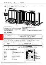
Page 36: ...Pin 5 6 Uscita arresto chiusura Pin 7 8 Uscita arresto apertura Pin 9 Ingresso test Pin 10 Non occupato 6 Panoramica 6 1 LED di segnalazione In assenza di un messaggio di errore il LED power indica la funzione di controllo breve spegnimento All emissione di un messaggio di errore il numero di impulsi emessi indica l errore LED POWER verde Controllo del funzionamento spegnimento breve Messaggio di ...

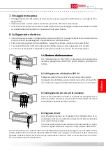
Page 37: ...sul pin 4 del con nettore 8 2 Collegamento alla bobina SPK 54 Collegare la bobina fissa ai pin 1 2 senza badare alla polarità Il collegamento alla bobina avviene tramite i connettori ad innesto for niti in dotazione oppure saldando direttamente il cavo ai connettori 8 3 Collegamento dei circuiti di comando Ai pin 5 6 è disponibile il circuito di comando da sorvegliare per la chiusura arresto chius...

Page 38: ... resistenza non deve essere maggiore di 500Ω Se non viene utilizzato un canale deve essere terminato con una resistenza di 8 2 kΩ I bordi mobili BSS vengono collegati alla bobina mobile A tal fine il BSS CHIUSURA mobile viene collegato ai morsetti C della bobina mobile ed il BSS APERTURA opzionale ai morsetti O Figura 2 collegamento di più sensori qui nell esempio bordo sensibile di sicurezza Dopo...

Page 39: ...pento ciclicamente per breve tempo In presenza di un errore interno il riconoscimento dell errore viene emesso mediante il numero di impulsi Se si accende il LED FAULT CLOSING o il LED FAULT OPENING significa che nel sistema è presente un anomalia 10 Avviamento e controllo del funzionamento Dopo aver eseguito tutti i collegamenti elettrici e collegato la tensione di alimentazione è necessario cont...

Page 40: ...estituiti alla ASO che provvede a smaltirli correttamente 13 Dati tecnici Bassissima tensione UE 24 V DC 10 Potenza assorbita PE 0 75 W Consumo di corrente IE 35 mA Tensione di alimentazione Resistenza terminale dei bordi sensibili di sicurezza valore nominale Rnom 8 2 kΩ soglia superiore RAO 20 0 kΩ soglia inferiore RAU 2 5 kΩ Tempo di intervento ta 30ms Tempi di commutazione Peso ca 15 g Campo d...

Page 41: ...ormi ai requisiti fondamentali per la sicu rezza e la salute previsti dalle seguenti direttive e norme CE Direttiva sulle macchine 2006 42 CE EN ISO 13849 1 2008 EN ISO 13849 2 2008 EN 61000 6 2 2005 EN 61000 6 3 2007 La presente dichiarazione di conformità non esonera il progettista produttore della macchina dall obbligo di verificare la conformità alla direttiva CE della macchina comp lessiva in...

Page 42: ...42 ...

Page 43: ...lemmen 46 7 Mechanische bevestiging 47 8 Elektrische aansluiting 47 8 1 Voedingsspanning 47 8 2 Aansluiting vaste spoelkern 47 8 3 Aansluiting stuurstroomkringen 47 8 4 Testsignaal 47 48 9 Aansluiting van de signaalgevers 48 9 1 Aansluiting aan de spoelkern SPK 54 48 9 2 Aansluiting van meerdere signaalgevers per signaalgevercircuit 48 10 Inbedrijfstelling en Functiecontrole 49 11 Foutendiagnose 4...

Page 44: ...oerd De veiligheidsvoorschriften betreffende elektrotechniek en die van de bedrijfsvereniging moeten in acht worden genomen Het relais dient bij werkzaamheden hieraan spanningsvrij geschakeld op spanningsvrijheid gecontroleerd en tegen opnieuw inschakelen beveiligd te worden Als de halfgeleideruitgangen extern met een spanning gevoed worden moet worden gegarandeerd dat deze bij werkzaamheden aan h...

Page 45: ...circuits met veiligheidscontactlijsten permanent op activering of onderbre king kabelbreuk Bij een storing wordt aan het betreffende veiligheidscontactlijstcircuit éé n van de twee stopcommando s toegewezen stop in open richting of stop in dicht richting Om een ruststroombewaking van het complete systeem mogelijk te maken is in de eindlijst van het veiligheidscontactlijstcircuit een afsluitweersta...

Page 46: ...VDC Pin 4 GND Pin 5 6 uitgang stop dicht beweging Pin 7 8 uitgang stop open beweging Pin 9 testingang Pin 10 niet gebruikt 6 Toesteloverzicht 6 1 Signaalweergaven Indien er geen foutmelding is wordt via de power LED deze controlefunctie gemeld LED gaat kort uit Bij een foutmelding geeft het aantal pulsen de fout aan LED POWER groen Functiecontrole kort uit Foutmelding pulsen LED FAULT OPEN rood St...

Page 47: ... pin 4 8 2 Aansluiting vaste spoelkern Aan de pin 1 2 moet de vaste spoelkern aangesloten worden waarbij de polariteit om het even is De aansluiting aan de spoelkern gebeurt via de meegeleverde krim phulzen of door direct vastsolderen van de leiding aan de stekker 8 3 Aansluiting stuurstroomkringen Op pins 5 6 is de te bewaken stuurstroomkring voor de dicht be weging Stop Closing en op de pins 7 8...

Page 48: ...500Ω niet overschrijden Afbeelding 1 Schakelaansluiting op spoelkern Als een kanaal niet gebruikt wordt moet dit kanaal bezet worden met een 8 2kΩ weer stand De meebewegende lijsten SKL s worden met de meebewegende spoelkern verbonden Hiertoe dient de meebewegende SKL DICHT bewe ging met de aansluiting C van de meebewegende spoelkern en de optionele SKL OPEN beweging met de aansluiting O verbonden...

Page 49: ...worden uitgeschakeld Is er een interne fout wordt via het aantal pulsen een foutmelding gegeven Gaat de LED FAULT CLOSING of LED FAULT OPENING branden is er een fout in het systeem 10 Inbedrijfstelling en Functiecontrole Na de overeenkomstige aansluiting van alle elektrische verbindingen en inschakeling van de voedingsspanning moet de poort op correcte functie gecontroleerd worden Daartoe moeten a...

Page 50: ... neemt de producten ook graag terug om voor de afvoer volgens de voorschriften zorg te dragen 13 Technische gegevens extra lage spanning UE 24 V DC 10 Vermogensopname PE 0 75 W Stroomverbruik IE 35 mA Voedingsspanning Aansluitweerstand veiligheidscontactlijsten nominale waarde Rnom 8 2 kΩ bovenste schakelwaarde RAO 20 0 kΩ onderste schakelwaarde RAU 2 5 kΩ Reactietijd ta 30ms Schakeltijden Gewicht...

Page 51: ...oet aan de desbetreffende fundamentele veiligheids en gezondheids eisen uit de volgende EG richtlijnen en normen EG machinerichtlijn 2006 42 EG EN ISO 13849 1 2008 EN ISO 13849 2 2008 EN 61000 6 2 2005 EN 61000 6 3 2007 Deze verklaring van overeenstemming ontbindt de constructeur fabrikant van de machine niet van zijn plicht om de conformiteit van de totale machine waarop dit product wordt aangebr...

Page 52: ...gen en drukfouten Technische en bedrijfsrelevante wijzigingen met betrekking tot de producten en toestellen in deze documentatie zijn ten allen tijde ook zonder vooraan kondiging voorbehouden 12 DB 03 100 Technical Specifications Rev 01 Subject to technical modifications No liability can be assumed for errors or misprints We reserve the right to make technical and operationally relevant changes to...

Reviews: