Asko DW90 Series Service Manual Download Page 14

Service manual DW90

14

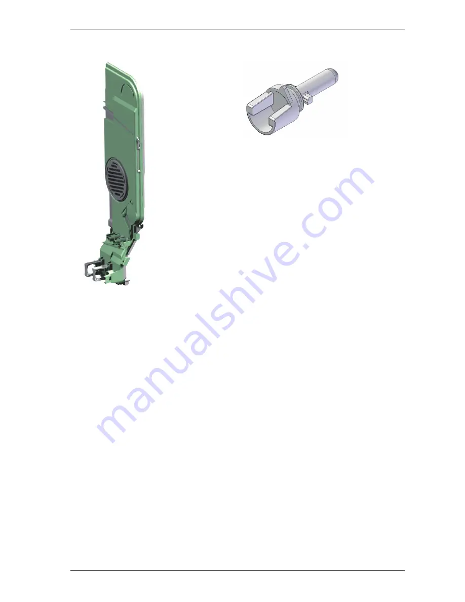
Component description

Air gap

The air gap is found next to the cleaning 
compartment. It comprises channels through 
which the incoming water flows into the 
cleaning compartment. These channels also 
contain an anti-backflow device and the 
flow sensor through which the water passes. 
Certain models are equipped with a water 
pocket that collects water used for the water 
softener (only machines with a water softener). 
The air gap also works as a channel of air taken 
in during the drying phase, as well as a pressure 
relief for excess air when opening and closing 
the door. On machines with Turbo Drying 
Express (TDE) a lid is mounted on the inside 
of the air gap. If there is condensation in the 
kitchen interiors, make sure the lid is correctly 
fitted.
 

Purpose:

 To prevent dirty water from the 

cleaning compartment being sucked back into 
the water supply, and lead air to and from the 
container.

Thermistor

The thermistor for temperature measurement 
is located at the front edge of the bottom 
drain. The thermistor measures and controls 
the water temperature, which can be up to 
70°C (158°F). If the thermistor short-circuits or 
loses contact with the CU, or of the thermistor 
does not register a temperature increase of 
5°C (41°F) within 10 minutes of the element 
being activated, the element is switched off and 
a fault code is indicated. This is only indicated 
in the service menu. The thermistor is of the 
NTC type (Negative Temperature Coefficient), 
i.e. its resistance decreases as temperature 
increases.
 

Purpose:

 To control the water temperature during 

the dishwashing process.

Light

The light is a 5 W/12 V halogen bulb powered 
by the control unit via a micro switch. The 
lamp is activated when the door is opened 
more than 5° and automatically deactivated 
when the door has been open for more 
than 30 minutes. The control unit features 
protective components that limit the current 
to the light in case of a short circuit or if a bulb 
with too high a power rating is fitted. The 
bulb can be replaced from inside the cleaning 
compartment.

Summary of Contents for DW90 Series

Page 1: ...Service manual Dishwasher DW90...

Page 2: ...Service manual DW90 2...

Page 3: ...Wiring diagram 18 Program flow description 20 Troubleshooting 22 Dishwashing results 22 Common faults 22 Water level DW90 23 Fault indicators 24 Fault and information codes 25 DW90 1 25 DW90 2 26 DW9...

Page 4: ...ice updated FH 05 2011 11 29 Updated wiring diagram and added information about Anti siphon ISC 06 2012 02 02 Updated service menu for 90 2 Changed description how to set TDE HWC AN 07 2012 03 16 Inst...

Page 5: ...f the inside of the door where the machine s model designation is specified The first two digits of the serial number specify the year of manufacture while the third and fourth digits specify the week...

Page 6: ...ty for example water pressure electrical supply drainage The machine operates normally No deviations can be found The customer probably needs to be informed about proper use of the machine If necessar...

Page 7: ...he front of the panel The main power switch is on the top PRO G START STOP DW90 3 The machine has 16 set programs and the touch buttons and display are on the top The number of options and settings va...

Page 8: ...kg 60 kg 126 lbs 132 lbs with water softener XXL Weight integrated 49 kg 52 kg 108 lbs 115 lbs with water softener XL 50 kg 53 kg 110 lbs 117 lbs with water softener XXL Water pressure 0 03 1 0 MPa 0...

Page 9: ...ry winding 76 ohm 8078087 Drain pump 200 240 V 50 Hz 16 L 4 2 gallon min 148 ohm 8078089 Drain pump 120V 60 Hz 16 L 4 2 gallon min 26 ohm 8078084 2 3 Spray arm diverter 230 V 50 60 Hz 8 5 kohm 8078085...

Page 10: ...n description Here we describe the function and specification of the most important components Certain components are found only in more highly specified machines or in particular markets See the Trou...

Page 11: ...er the spray arm hub on the underside of the cleaning compartment The water from the circulation pump flows through the spray arm diverter which alternates the flow of water between the upper and lowe...

Page 12: ...s started Fan The fan is fitted to the top edge of the inner door and comprises a fan motor a fan housing a venting duct a double sided impeller a damper and a Wax motor that controls the damper funct...

Page 13: ...rogram is paused and power to certain components circulation pump valves and more is cut The program continues where it left off when the door is closed If a program is running the machine indicates t...

Page 14: ...he thermistor for temperature measurement is located at the front edge of the bottom drain The thermistor measures and controls the water temperature which can be up to 70 C 158 F If the thermistor sh...

Page 15: ...water collects on the machine s bottom plate The micro switch is normally closed When it is activated it breaks the circuit to the CU the drain pump starts the program is interrupted and the machine...

Page 16: ...midity level close to that before the drying program began Purpose To make sure the drying program runs as long as necessary to ensure a satisfactory drying result Status Light To the right at the bot...

Page 17: ...which ensures that over or under pressure never occurs in the machine This prevents the machine from either being emptied of water or sucking water from the drain As an extra security measure the drai...

Page 18: ...32 OHM 110 OHM 56 OHM 25 OHM 150 OHM 85 OHM 2 6 KOHM 8 5 KOHM 0 95 KOHM 0 5 KOHM 3 9 KOHM 2 KOHM 0 65 KOHM 0 65 KOHM 3 KOHM 2 3 KOHM 10 KOHM 1 1 KOHM 0 18 KOHM 0 85 KOHM 0 22 KOHM 0 90 KOHM S AT ROOM...

Page 19: ...HM 56 OHM 25 OHM 150 OHM 85 OHM 2 6 KOHM 8 5 KOHM 0 95 KOHM 0 5 KOHM 3 9 KOHM 2 KOHM 0 65 KOHM 0 65 KOHM 3 KOHM 2 3 KOHM 10 KOHM 1 1 KOHM 0 18 KOHM 0 85 KOHM 0 22 KOHM 0 90 KOHM RESISTANCES AT ROOM TE...

Page 20: ...ime 90 sec Minimum time 76 sec 11 Drain process 120 sec Maximum time Time is controlled by level sensor Main wash 12 Inlet process 255 sec Maximum time Inlet time is controlled by a flow meter 13 Circ...

Page 21: ...ted 2 Inlet process 255 sec Maximum time Inlet time is controlled by a flow meter 3 Circ pump 3 sec 4 Pause 30 sec If water temperature is 30 C ECO program starts DW90 1 5 Circ pump 30 sec 6 Pause 5 s...

Page 22: ...emperature Film or marks on dishes after washing Is the water softener cover properly tightened Is the rinse aid dispenser correctly adjusted Is the water softener correctly adjusted Is there any salt...

Page 23: ...lower spray arm hub In the event of too low water level the filter in the inlet valve must always be checked and rinsed clean of any sediment The inlet hose with a 3 4 connection at both ends has a fi...

Page 24: ...T Push button F Fault code or plain text on display D Display I Indication DW90 3 IR M2 8 M2 1 START PROG STOP S5 M1 1 M1 28 S3 S2 S4 DISPLAY I1 1 I7 I8 I1 3 I6 I2 1 I2 2 I3 I10 I4 I5 I1 2 I11 I9 545...

Page 25: ...40 Inlet valve leakage Water intake detected when inlet valve deactivated in program sequence or standby In this case the machine attempts to close the valve by opening it for 2 seconds and then clos...

Page 26: ...40 Inlet valve leakage Water intake detected when inlet valve deactivated in program sequence or standby In this case the machine attempts to close the valve by opening it for 2 seconds and then clos...

Page 27: ...osing it again If water flow through the valve is still detected any current program is stopped drain pump activated Check Leak through inlet valve and flow meter Pressure sensor fault Pressure sensor...

Page 28: ...power switch 1 0 Wait until the LCD display lights up before next step PROG START Within 5 seconds press T1 and then press T2 and keep them pressed for 5 seconds L1 L3 and L6 indicates that the servic...

Page 29: ...wash cycle not in normal program default setting Y 2 Fan works in sequence during the wash cycle even during normal program START ECO PROG E 0 ECO off default setting E 1 ECO on if machine connected t...

Page 30: ...alue x 0 068 s L 5 Time controlled water intake increases by 5 L 10 Time controlled water intake increases by 10 L 15 Time controlled water intake increases by 15 START T8 T1 LCD1 T3 T4 T5 T6 T7 T2 D1...

Page 31: ...sequence during the wash cycle even during normal program START TDE HWC PROG A 0 Turbo Drying Express and Heating Water Circuit off default setting A 1 Turbo Drying Express on A 2 Heating Water Circu...

Page 32: ...all alternate between positions 1 and 3 every 30 seconds turbidity XX in volts Testing Heat XX C Circulation pump and heater on max 75 C 167 F temperature shown in C or F depending on the machine sett...

Page 33: ...etting Contrast 1 LCD contrast 1 Contrast 2 LCD contrast 2 Contrast 1 LCD contrast 1 S4 TDE S3 Turbo Drying on Turbo Drying Express on default setting Turbo Drying off Turbo Drying Express off S4 Fan...

Page 34: ...The status lights LEDs change colour every five seconds switching between blue red and green The LCD display backlight remains on constantly The store program can be run with the door open or closed...

Page 35: ...Service manual DW90 35 PERSONAL NOTES...

Page 36: ...the cleaning compartment along the rear edge and tipping it forward to create more space to work with Remove the three screws on each side of the cleaning compartment Take one of the M6 screws with O...

Page 37: ...ts where the micro switch for the overflow guard is disconnected it is important that the cables are correctly reattached If reattached incorrectly the machine will not start Connect the 2 pin connect...

Page 38: ...Service manual DW90 38 PERSONAL NOTES...

Page 39: ...Service manual DW90 39 PERSONAL NOTES...

Page 40: ...We reserve the right to make changes www asko com...

Reviews: