


4.
SETTING UP THE UNIT:
NOTE:
The AEU-425FO is manufactured
with 6.3A (250V rated) fuses installed, if
operating with a 230V power source,
change to the 3.15A fuses before
operation.
1.
Unpack the Console Case and attach the
power cord to the lower front of the Electric
Control Console and plug into a grounded
electrical receptacle. The AEU-425FO has
dual voltage auto-detection circuitry that
allows the unit to operate while using a
power source that is either 120V or 230V
and either 50Hz or 60Hz.
NOTE:
Be sure
the correct Fuse and Line Cord is used for
each voltage (see pg. 15).
2.
Connect the motor/cord assembly to the
receptacle on the lower front panel of the
Electric Control Console (see Fig. 7):
a.)
Gently press cord connector body
against receptacle on the console and
carefully turn connector until its pins align
with, and engage, the receptacle socket;
b.)
Turn the collar on the cord connector
body clockwise to lock the connector onto
the receptacle. Hand tighten only.
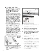
3.
Attach the appropriate “E” Type handpiece
to the motor. See Figs. 1, 2 & 3.
4.
Attach the supplied AE-7P On/Off Foot
Switch to the connector on the front of the
Electric Control Console marked “Foot
Switch”.
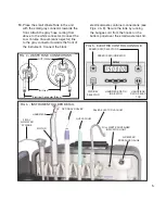
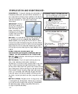
5.
Move the 3-Way Air/Water Syringe from the
travel clip and place it in the left holder on
the front of the unit.
6.
Remove the Optional Ultrasonic Scaler
from its travel pouch and connect an
Instrument Tip.
7.
Connect the Air Reserve Bottle above “Air”
marking (the right rear connection on the
right side of the unit.)
8.
Fill the Water Supply Bottle with clean
water and connect to the cap with the
pressure gauge.
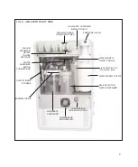
9.
Place the large Waste Tank in the unit with
the large white connection to the rear left of
the instrument and attach the white
connection coming from the vacuum motor.
Connect the high volume vacuum (HVE) to
the large gray connector towards the front
of the instrument. Connect the black
electrical connector to one of the black
electrical waste container connections (see
Figs 4 & 8). Secure tank by running
bungee cord from hooks on bottom panel
over Waste Tank lid.
FIG. 2 - HANDPIECE ALIGNMENT-
MOTOR / HANDPIECE ALIGNMENT
FIG. 1 - MOTOR CONNECTION -
FIG. 3 - MOTOR BULB COVER
HANDPIECE
ALIGNMENT
TAB
BULB COVER
MOTOR
ALIGNMENT
SLOT
(Bulb Cover
Removed)
(Bulb Cover
Removed)