


4
ADC-02CF
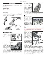
7 CONNECTING BACKREST
CYLINDER:
Lift the backrest
A
upright while simultane‑
ously guiding the clevis pin
B
on the end of the backrest cyl‑
inder into the latch
C
on the
backrest frame, until they have
securely latched
D
.
D
B
C
WARNING:
Make sure the clevis pin is centered in the latch and
not off to one side. Both ends of the clevis pin must be securely
latched.
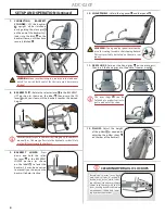
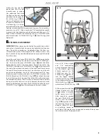
8 BACKREST LIFT:
Rotate the selector lever
A
to the BACKREST
LIFT position (as shown on the label
B
) then pump the lift
lever
C
with your foot until the backrest reaches the desired
height.
B
A
C
Never attempt to raise the backrest by lifting up on the backrest
manually, as this may pull air into the hydraulic system! Only
use the lift lever to raise the backrest.
9 BACKREST LOWER:
Press
down and hold the selec‑
tor lever
A
in the BACKREST
LOWER position (as shown
on the label
B
) to lower the
backrest; it may be necessary
to manually push down on the
backrest to help it recline.
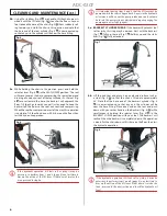
10 CHAIR PANELS:
Unfold the leg panel
A
and foot panel
B
.
A
B
WARNING:
The leg and foot panels must not be
used for seating to reduce chair tipping hazard.
Patients must only be seated on the main seat
panel.
11 ARM SLINGS:
Fold out the hand grips
A
on the arm posts,
then insert the hand grips into the ends of the arm slings
B
.
A
A
B
B
The arm slings
C
can be
folded up to make it easier to
get in and out of the chair.
12 PILLOW:
Adjust the height
of the pillow
A
as needed by
adjusting the pillow straps
B
on the rear of the backrest.
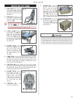
Rotate the selector lever back
Rotate the selector lever back
and forth to clear a lockup. A
and forth to clear a lockup. A
lockup may occur while lower‑
lockup may occur while lower‑
ing the seat if the backrest frame
ing the seat if the backrest frame
comes into contact with the lift
comes into contact with the lift
lever, causing a conflict between
lever, causing a conflict between
simultaneous lifting and lower‑
simultaneous lifting and lower‑
ing hydraulic operations.
ing hydraulic operations.
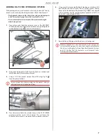
CLEARING HYDRAULIC LOCKUPS
1 2
A
A
B
C
C
A
B
SETUP AND OPERATION
(Continued)
Summary of Contents for ADC-02CF
Page 14: ...14 ADC 02CF ...
Page 15: ...15 ADC 02CF ...