background image

© 2020 ASCO Power Technologies. All Rights Reserved

For troubleshooting, call technical assistance at 1-800-237-4567 or [email protected]

7

IO-75066

01/2020

ASCO Model 318 

Surge Protective Device (SPD)

MODEL

MCOV

APPLICATION

WYE

318120YP05A3FN10

150V

208Y/120V (No N-G required)

318120YP05A3GN10
318120YP05N4FN10

208Y/120V (N-G suggested)

318120YP05N4GN10
318127YP05A3FN10

180V

220Y/127V (No N-G required)

318127YP05A3GN10
318127YP05N4FN10

220Y/127V (N-G suggested)

318127YP05N4GN10
318277YP05A3FN10

320V

480Y/277V (No N-G required)

318277YP05A3GN10
318277YP05N4FN10

480Y/277V (N-G suggested)

318277YP05N4GN10
318347YP05A3FN10

420V

600Y/347V (No N-G required)

318347YP05A3GN10
318347YP05N4FN10

600Y/347V (N-G suggested)

318347YP05N4GN10

DELTA

318240DP05A3FN10

270V

240V (No N-G required)

318240DP05A3GN10
318240DP05G3FN10

240V (N-G suggested)

318240DP05G3GN10
318480DP05A3FN10

550V

480V (No N-G required)

318480DP05A3GN10
318480DP05G3FN10

480V (N-G suggested)

318480DP05G3GN10

Summary of Contents for Power Technologies 318

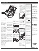
Page 1: ...Surge Protective Devices Installation Operation Manual Model 318 ...

Page 2: ...you to potential personal injury hazards Obey all safety messages that follow this symbol to avoid possible injury or death DANGER DANGER indicates a hazardous situation which if not avoided will result in death or serious injury WARNING WARNING indicates a hazardous situation which if not avoided could result in death or serious injury CAUTION CAUTION indicates a hazardous situation which if not ...

Page 3: ... Always use a properly rated voltage sensing device to confirm power is off Replace all devices doors and covers before turning on power to this equipment This equipment must be effectively grounded per all applicable codes Use an equipment grounding conductor to connect this equipment to the power system ground Confirm that the Surge Protective Device voltage rating on the module or nameplate lab...

Page 4: ...o be applied to terminal screws is 14 75 in lb 1 67 N m 5 The Model 318 has optional remote status contacts The contacts may be wired using either the normally open NO or normally closed NC positions depending on the application See Remote Output Diagram The contacts are rated 125VAC 3 Amps maximum 6 Turn on power and verify operation Figure 1 Single Phase Figure 2 Split Phase Figure 3 WYE Figure ...

Page 5: ...ency 47 63 Hz Peak Surge Current 50 kA per mode Connection Type Parallel Operating Temperature 40 C 40 F to 85 C 185 F Operating Humidity 0 to 95 non condensing Status Indication Visual Indicator Tabs Dry Contact optional Form C Contact Rating 125VAC 3Amps maximum Form C Relay Wire Size 16 30 AWG Torque 2 0 in lb Response Time 1 0 ns Polymeric Enclosure UL 94 V0 Flame Rated Weight lb kg per pole 0...

Page 6: ...18230NP05A1GN10 2 318230NP05A1FN10 240V N G suggested 2 318230NP05A1GN10 318277NP05A1FN10 320V 277V No N G required 318277NP05A1GN10 2 318277NP05A1FN10 277V N G suggested 2 318277NP05A1GN10 2 Pole Split Phase 318120SP05A2FN10 150V 120 240V No N G required 318120SP05A2GN10 318120SP05A2FN10 120 240V N G suggested 318120SP05A2GN10 318120NP05A1FN10 120 240V N G suggested 318120NP05A1GN10 318127SP05A2F...

Page 7: ... 220Y 127V No N G required 318127YP05A3GN10 318127YP05N4FN10 220Y 127V N G suggested 318127YP05N4GN10 318277YP05A3FN10 320V 480Y 277V No N G required 318277YP05A3GN10 318277YP05N4FN10 480Y 277V N G suggested 318277YP05N4GN10 318347YP05A3FN10 420V 600Y 347V No N G required 318347YP05A3GN10 318347YP05N4FN10 600Y 347V N G suggested 318347YP05N4GN10 DELTA 318240DP05A3FN10 270V 240V No N G required 318...

Page 8: ...or any errors or omissions Dimensions in mm Uses standard 35mm DIN Rail 4 pole shown Width Length Height 1 Pole 0 70 in 17 8mm 4 09 in 103 9mm 2 70 in 68 5mm 2 Pole 1 39 in 35 5mm 4 09 in 103 9mm 2 70 in 68 5mm 3 Pole 2 10 in 53 3mm 4 09 in 103 9mm 2 70 in 68 5mm 4 Pole 2 80 in 71 0mm 4 09 in 103 9mm 2 70 in 68 5mm WIRE MARKER LOCATION 2 80 71 0mm 0 41 10 5mm TYP 0 70 17 8mm TYP 1 09 27 7mm 0 27 6...

Reviews: