laserBIRD™ Installation and Operation Guide
26
26
26
26
laserBIRD
Alignment Procedure
By default, most trackers return position and orientation of a sensor relative to a measurement
source (transmitter, Scanner, etc). In many instances however, it is useful to have the tracker return
the position and orientation of an object relative to a chosen reference frame. The
Reference
Frame
and
Angle Align
settings allow you to customize the laserBIRD for your specific tracking
requirements. If you're familiar with a procedure for determining these values, enter them as
shown in the
section above. This procedure provides a simple way to
determine the correct values for your installation, without the use of additional equipment.
Begin this procedure with the Scanner mounted at your desired position and orientation, and
not moving.
1.
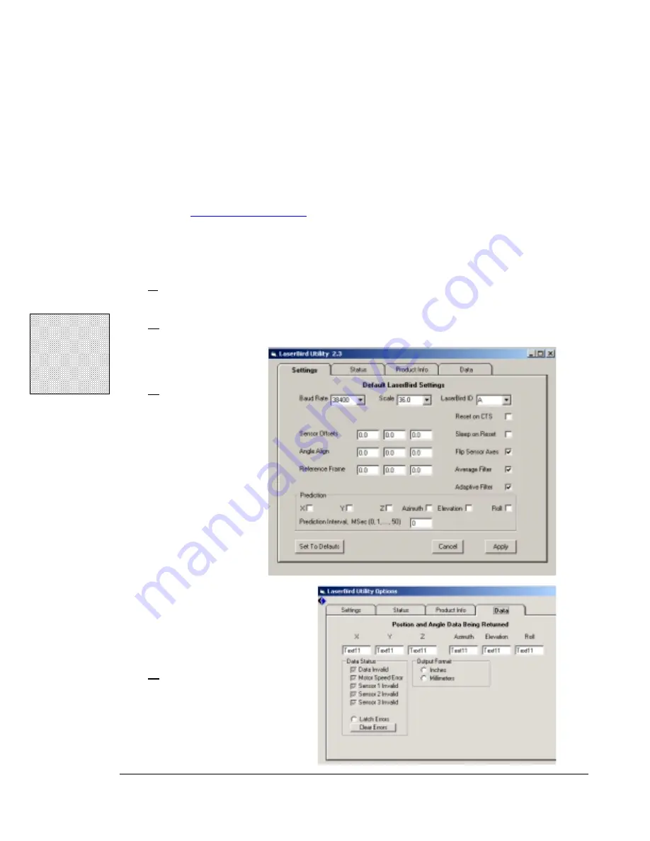
Make sure the laserBIRD is running and connected to the host PC where the
laserBIRD Utility has been installed.
2.
Start the utility by selecting
laserBIRD Utility
from the Ascension Technology
program group in the Windows® Start menu.
3.
Go to the
Settings
tab and
check that the
Angle Align
and
Reference
Frame
settings
are '0.0', and the
Flip Sensor Axes
setting is enabled.
Set the
Scale
to
'72.0'
If you had to alter
any setting, click 'Apply' to
send the laserBIRD the
updated value.
4.
Click on the
Data
tab and
look for streaming sensor
data.
!
Note:
You can also
download the
utility by visiting
Ascension's web
site.
Summary of Contents for laserBIRD
Page 3: ......
Page 5: ......
Page 7: ......
Page 11: ......
Page 21: ......
Page 32: ...3 Configuration and Basic Operation 25 25 25 25 Figure 3 3 Sensor Mounting Dimensions inches...
Page 42: ...3 Configuration and Basic Operation 35 35 35 35 Figure 3 6 Horizontal Field of View...
Page 43: ...laserBIRD Installation and Operation Guide 36 36 36 36 Figure 3 7 Vertical Field of View...
Page 45: ......


