Technical Specifications
Network Management SNMP-compatible management software, HTTP
management software, Telnet software
Connectors RS-232 (DB-9, female), RJ-45 (10/100Base-TX),
RJ-21 (10/100Base-TX),
MII (Media Independent Interface)
Spanning Tree Support IEEE 802.1d
MAC Address Table Size 1024
Dimensions Width: 17.1 inches (434.3 mm)
Height: 2.25 inches (57.2 mm)
Depth: 14.5 inches (368.3 mm)
Weight 11 pounds (5 kilograms)
Power Specifications
Voltage Range: 100 to 250 VAC
Frequency Range: 50/60/440 Hz
Maximum current range: 1.6A
Environmental Specifications
Temperature Operating: 0
°
to 40
°
C
Relative Humidity Operating: 5% to 85% (non-condensing)
Standards Compliance MIB II, RMON (4 groups: 1,2,3,9), BootP, DHCP,
IEEE 802.3, IEEE 802.3u, IEEE 802.1d
Safety UL, CSA, VDE, TUV
Emissions FCC Class A, EN55022, CE
06-00437-00
LEDs
Asking for Assistance
Technical Support Hours: 6:00 a.m. to 5:00 p.m. Pacific Standard Time, Monday-Friday
For troubleshooting tips, refer to Appendix A in the IntraSwitch 5324 User’s Manual.
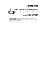
1. Using a straight-through RS-232 cable with a 9-pin male D-subminiature plug at
one end, connect a stand-alone terminal or a PC with a terminal emulator to the
Console port on the IntraSwitch.
2. Make sure both units are powered on.
If using a PC with a terminal emulator, make sure it is configured with the following
terminal settings:
• Bits Per Second: 9600 • Stop Bits: 1
• Data Bits: 8 • Flow Control Hardware: None
• Parity: None
3. After connecting to the switch, the Local Management Interface Main Menu appears.
4. Type c to open the Configuration Menu. The “Enter Password” prompt appears.
5. Type Asante at the “Enter Password” prompt. The password is case sensitive.
6. Press return. The Configuration Menu appears.
7. Type i to open the TCP/IP Parameter Menu. The TCP/IP Parameter Menu appears.
8. Type i to select the option “Set IP Address.”
9. Type a valid IP address for the IntraSwitch at the prompt, then press return.
▲
Depending on your network configuration, you may also need to set subnet
mask and default router information for the IntraSwitch. See “Configure TCP/IP
Parameters” in Chapter 4 of the User’s Manual for details.
10. Type q to return to the Configuration Menu.
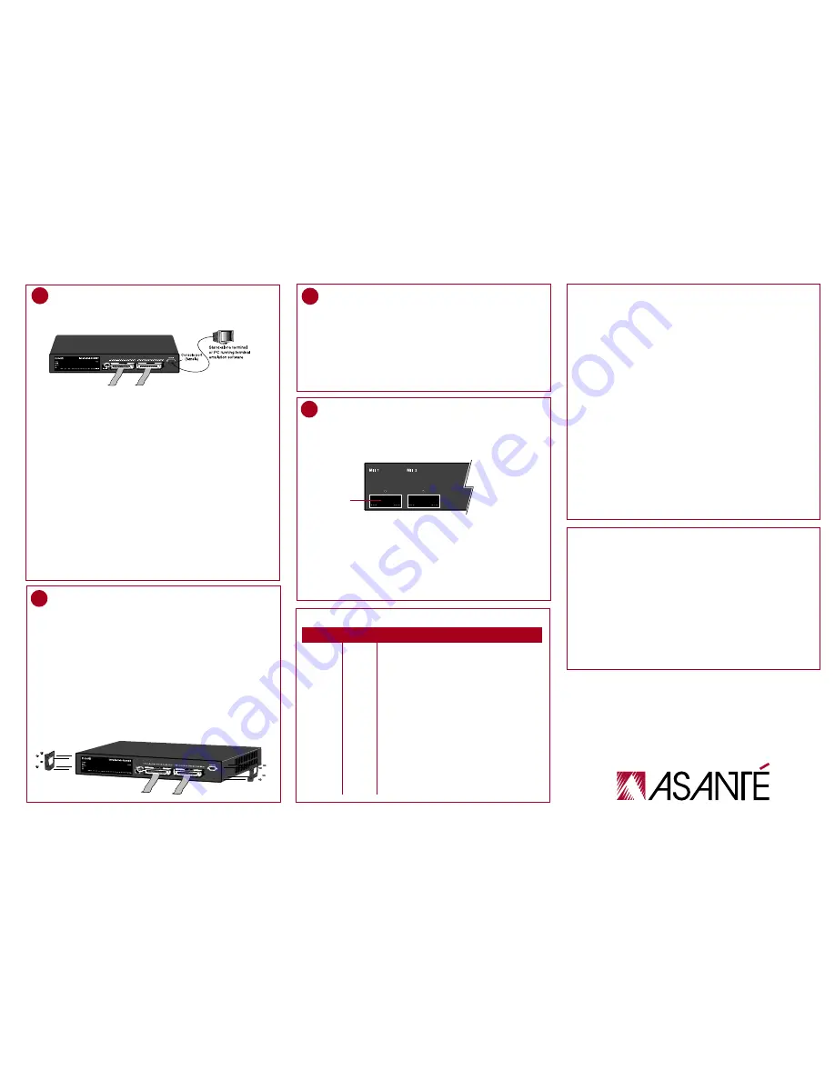
To install an MII module:
1. Unscrew the metal cover from the front of an MII expansion slot on the
IntraSwitch’s back panel using a small Phillips screwdriver.
2. Align the bottom of an MII module with the rails on the inside of the expansion slot.
3. Slide the MII module into the expansion slot until it stops, then push the module
in until it seats with the connector.
4. Screw the module into place using the screw that came with your MII module
(this secures the module’s connection).
After the MII module is installed, connect the port to a network device.
5
MII Expansion Slots
The IntraSwitch has two optional Media Independent Interface (MII) expansion slots
on the switch’s back panel which allow for the addition of various types of media
access modules, including 10/100 TX, 100Base-FX, and 10Base-FL.
The MII modules are sold separately and comply with IEEE 802.3 and 802.3u
(10/100Base-T and 100Base-FX) specifications.
3b
Console Configuration
The IntraSwitch can be installed in a standard 19-inch EIA RS-310C equipment rack.
The switch can also be placed on a horizontal surface with support capabilities of
11 pounds (5 kilograms).
Equipment Rack Installation
To install the IntraSwitch in an equipment rack:
1. Mount one rack bracket (supplied) on each side of the switch’s chassis with the
screws provided.
2. Place the IntraSwitch in the equipment rack.
3. Use the four remaining screws to secure the switch by its mounting brackets to the
equipment rack.
▲
Important: Make sure the switch is supported until all four remaining screws for
each bracket are installed. Failure to do so could cause the switch to fall, resulting in
personal injury or damage to the unit, or both.
4A
Desktop Placement
The IntraSwitch has four rubber self-adhesive feet that can be applied to the bottom
of the chassis to enable desktop/free-standing installation of the unit.
1. Turn the switch over so that the bottom of the chassis faces up.
2. Peel the protective backing off of each rubber foot.
3. Position each rubber foot over the recessed areas near the four corners of the switch.
4. Press each rubber foot into place.
5. Place the switch on a horizontal surface with a minimum area of 17.1" x 14.5".
Telephone (800) 622-7464
Fax (801) 566-3787
BBS (408) 432-1416
FTP Archive ftp.asante.com
Internet mail [email protected]
World Wide Web site www.asante.com
Here’s how to reach Asanté Technical Support.
METAL COVER
LED Color Meaning
Power green The IntraSwitch is receiving electrical power.
100Mbps green 10/100 port or an installed MII expansion port is
operating at 100Mbps speed.
Note: These LEDs only function with ports capable of
operating at 100Mbps speed (i.e., the 10/100 port or
an installed MII module).
Max Util amber The corresponding port’s receive buffer is full
(maximum utilization).
FDP/Col amber Indicates full duplex mode on the 10/100 port or
on an installed MII expansion port.
Indicates a collision at the switching port for those
ports operating in half-duplex mode.
Data green Traffic activity is occurring on a port (transmit [TX] or
receive [FIX]).
Link green A node or other network device is properly connected
to the corresponding port.
4
Rack Mounting/Desktop Placement