

To use the IntraSwitch 5308FL as a managed switch, it must be configured with an IP
address. This can be accomplished in one of two ways:
•
Automatically using BootP (default)
•
Manually via the Console port
BootP Configuration
The IntraSwitch 5308FL is shipped with BootP/TFTP support. BootP allows the
IntraSwitch 5308FL to be automatically configured with an IP address when the Intra-
Switch 5308FL is connected to the network and is powered on, if your network contains
a BootP server configured with available, valid IP addresses.
1. Make sure your network has a BootP server configured with a valid IP address
entry for the IntraSwitch 5308FL.
2. When the IntraSwitch 5308FL is connected to the network and is first powered
on, it automatically transmits a BootP request across the network (up to 5 times)
until it receives a valid IP address from the BootP server.
3. After an IP address is received, the IntraSwitch 5308FL is ready for management
via in-band access.
If an IP address is not received, the IntraSwitch 5308FL will need to be manually
configured with an IP address. See "Console Configuration" below.
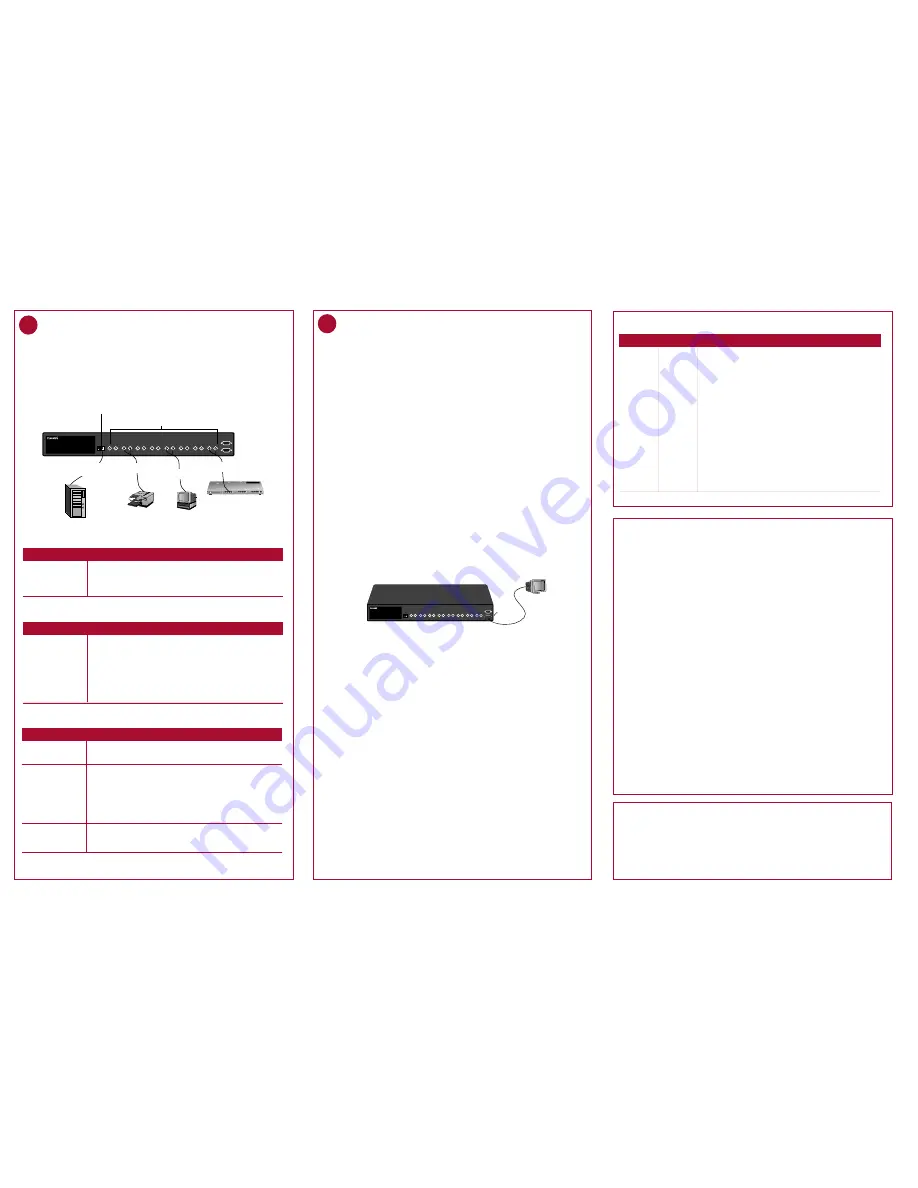
Console Configuration
To configure the IntraSwitch 5308FL with an IP address via the unit's Console port:
1. Using an RS-232 cable, connect a stand-alone terminal or a PC with a terminal
emulator to the IntraSwitch 5308FL's Console port.
2. Make sure both units are powered on.
If using a PC with a terminal emulator, make sure it is configured with the
following terminal settings:
3. After connecting the terminal to the IntraSwitch 5308FL , the Local Management
Interface Main Menu appears on the screen.
4. Type c to open the Configuration Menu.
The "Enter Password" prompt appears.
5. Type Asante at the "Enter Password" prompt.
The password is case-sensitive; enter it exactly as shown.
6. Press return.
The Configuration Menu appears.
7. Type i to open the Config TCP/IP Parameters Menu.
8. Type i to select the option "Set IP Address."
9. Enter the IP address to be assigned to the IntraSwitch 5308FL at the prompt,
then press return.
▲
Important: Depending on your network configuration, you may also need to set
subnet mask and default router information. See "System IP Configuration" in
Chapter 5 of the IntraSwitch 5308FL User's Manual for instructions.
10. Type q to return to the Configuration Menu.
IntraSwitch 5308FL
100 Mbps
Max Util
FDP / COL
Data
Link
10/100 1 2 3 4 5 6 7 8 MII 1 MII 2
10/100
Console
RS-232
1
2
3
4
5
6
7
8
Stand-alone terminal
or PC running terminal
emulation software
Console port
(female)
5
Configure for Management
06-00367-00 Rev
. A
Asking for Assistance
Technical Support Hours: 6:00
A
.
M
. to 5:00
P
.
M
. Pacific Standard Time, Monday-Friday
For troubleshooting tips, refer to Appendix A in the IntraSwitch 5308FL User's Manual.
Telephone ................................. (800) 622-7464
Fax ............................................ (408) 432-6018
Fax-Back ................................... (800) 741-8607
Bulletin Board Service (BBS) .... (408) 432-1416
ARA BBS (guest login) .............. (408) 432-1416
AppleLink mail/BBS ............................. ASANTE
FTP Archive ................................ ftp.asante.com
Internet mail ..................... [email protected]
World Wide Web Site ..... http://www.asante.com
LED Indicators
Technical Specifications
Meaning
LED
Color
amber
The port is operating in full duplex mode.
FDP/Col
Power
green
The IntraSwitch 5308FL is receiving electrical power.
amber
The port's receive buffer is full (maximum utilization).
Note: It is normal to see these LEDs illuminate during extremely high
periods of network activity.
Max Util
green
Traffic activity is occurring on a port (transmit [TX] or receive [RX]).
Data
green
A node or other network device is properly connected to the port.
Link
100Mbps
green
The 10/100TX port or an installed MII expansion port is operating
at 100Mbps speed.
Note: This LED only functions with ports capable of operating at
100Mbps speed (i.e., the 10/100TX port or an installed 10/100TX or
100Base-FX module).
IntraSwitch 5308FL
100 Mbps
Max Util
FDP / COL
Data
Link
10/100 1 2 3 4 5 6 7 8 MII 1 MII 2
10/100
Console
RS-232
1
2
3
4
5
6
7
8
1
2
3
4
5
6
7
8
9
10
11
12
100BASE-TX Ports
4
3
2
1
5
6
7
8
Col
Pwr
9 10 11 12
Partition
Link/Receive
Uplink
or
AsantéFAST 100 TX Hub
Remove Before Stacking
Hub
10Base-FL ports: require dual 62.5/125 micron graded-index
multimode fiber-optic cables with dual ST connectors
10/100 port: requires
Category 5 cable
Category 5
straight-through cable
(100m max. length)
100Base-TX
Server
Printer
ST connector
(100m max. length)
10Base-T
Workstation
ST connector
(100m max. length)
ST connector
(100m max. length)
•
Bits Per Second: 9600
•
Data Bits: 8
•
Parity: None
•
Stop Bits: 1
•
Flow Control: None
To connect the IntraSwitch 5308FL to an Ethernet network:
1. Make sure the IntraSwitch 5308FL's power is off.
2. Connect network devices to the IntraSwitch 5308FL, following the cable
guidelines below.
3. Power on the IntraSwitch 5308FL.
4
Connect to the Network
10Base-FL ports Calbing Procedures
Cable Required
Connecting To
All Network Devices
Dual 62.5/125 micron graded-index multimode fiber-optic cable
with a dual ST connector.
10/100 Port Cabling Procedures
Cable Required
Connecting To
Network Station
Repeater/Hub
Repeater/Hub's
UPLINK port
Category 5 UTP (Unshielded Twisted-Pair) straight-through cable
(100 meters maximum) with RJ-45 connectors.
Category 5, UTP cross-over cable (100 meters maximum) with RJ-45
connectors.
Category 5, UTP straight-through cable (100 meters maximum) with
RJ-45 connectors.
MII Expansion Ports Cabling Procedures
Spanning Tree Support
IEEE 802.1d
MAC Address Table Size
1024
Dimensions
17.1" x 14.5" x 2.25" (434.3mm x 368.3mm x 57.2mm)
Weight
11 pounds (5 kilograms)
Power Specifications
Voltage Range:
100 to 250VAC
Frequency Range:
50/60/440Hz
Max. Current Range:
1.6A
Environmental Specifications
Temperature:
Operating: 0
°
to 45
°
C
Relative Humidity:
Operating: 5% to 85% (non-condensing)
Safety:
UL, CSA, VDE, TUV
Emissions:
FCC Class A, EN55022, CE
Network Management
SNMP-compatible management software, HTTP
management software, Telnet software
Connectors
RS-232 (DB-9 female), ST (10Base-FL ports),
RJ-45 (10/100TX port), MII (Media Independent Interface)
Standards Compliance
MIB II, RMON (4 groups: 1,2,3,9), BootP, DHCP,
IEEE 802.3, IEEE 802.3u, IEEE 802.1d
Connecting To — Cable Required
Expansion Module
100Base-FX Module
10/100TX Module
All Network Devices — dual 62.5/125 micron graded-index multimode
fiber-optic cable with an SC connector.
Network Station — Category 5 UTP (Unshielded Twisted-Pair) straight-
through cable (100 meters max.) with an RJ-45 connector.
Repeater/Hub — Category 5, UTP cross-over cable (100 meters max.)
with RJ-45 connectors.
Repeater/Hub's UPLINK port — Category 5, UTP straight-through cable
(100 meters max.) with an RJ-45 connector.
10Base-FL Module
(ST connector)
All Network Devices — dual 62.5/125 micron graded-index multimode
fiber-optic cable with a dual ST connector.


