

MII 1 (Port 26)
MII 2 (Port 27)
Slide Module into Slot
Remove Cover
Quick Installation Guide
Additional materials required:
•
Network cables — see step 4 "Connect to the Network," to determine the type of
cables you will need to connect network devices to the IntraSwitch 5308FL
•
Phillips screwdriver — for rack-mounting the IntraSwitch 5308FL.
Package Contents
(1) Quick Installation Guide (this card)
(1) User's Manual
(1) Manual Addendum
(1) Registration card
The IntraSwitch 5308FL is shipped with the following items:
(1) IntraSwitch 5308FL Ethernet switch
(1) Power cord
(2) Rack-mounting brackets
(12) Standard Phillips screws
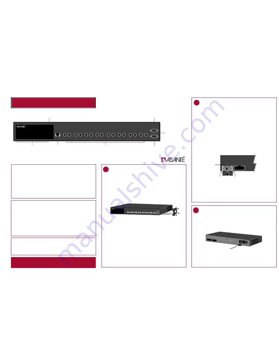
10/100TX port
auto-negotiating; RJ-45 connector
Eight 10Base-FL ports
with ST connectors
RS-232 Port
for out-of-band (with
modem) management
Console Port
for out-of-band
management
POWER
Power LED
MII Expansion Slots
(optional ports; located
on back of unit)
LEDs
IntraSwitch 5308FL
100 Mbps
Max Util
FDP / COL
Data
Link
10/100 1 2 3 4 5 6 7 8 MII 1 MII 2
10/100
Console
RS-232
1
2
3
4
5
6
7
8
IntraSwitch
™
5308FL
Overview
The Asanté IntraSwitch 5308FL is an 8-port 10Base-FL Ethernet switch that comes with
one 10/100 port and two MII (Media Independent Interface) expansion slots.
The MII expansion slots allows for the connection of 10/100Base-TX, 100Base-FX or
10Base-FL media access modules.
About This Guide
This guide provides instructions for mounting, installing, and connecting your IntraSwitch
5308FL to an Ethernet network. For information on managing the IntraSwitch 5308FL,
refer to the IntraSwitch 5308FL User's Manual included in your package.
Default Port Settings
The IntraSwitch 5308FL is shipped with the following default port configuration settings:
•
10Base-FL ports: half duplex
•
10/100TX port: auto-negotiation enabled
(auto-negotiates to 10 or 100Mbps half duplex)
•
Spanning Tree: enabled on all
ports
The IntraSwitch 5308FL can be installed in a standard 19-inch equipment rack. It can
also be placed on a stable, horizontal surface with support capabilities of 11 pounds.
Equipment Rack Installation
To install the IntraSwitch 5308FL in an equipment rack:
1. Place the IntraSwitch 5308FL on a flat, stable surface.
2. Locate a rack-mounting bracket (supplied) and place it over the mounting holes
on one side of the unit, as shown below.
3. Insert four screws (supplied) into the holes and tighten with a Phillips screw-
driver.
4. Repeat the two previous steps for the unit's other side.
5. Place the IntraSwitch 5308FL in an equipment rack.
6. Secure the IntraSwitch 5308FL to the equipment rack by screwing its mounting
brackets to the equipment rack.
Desktop Placement
The IntraSwitch 5308FL has four rubber feet on the bottom of the chassis that enable
desktop/free-standing placement of the unit.
For desktop/free-standing placement:
1. Place the IntraSwitch 5308FL on a flat, stable, horizontal surface with a mini-
mum area of 17.1" x 14.5" (434.3mm x 368.3mm) and support capabilities of
11 pounds (5 kg.).
IntraSwitch 5308FL
100 Mbps
Max Util
FDP / COL
Data
Link
10/100 1 2 3 4 5 6 7 8 MII 1 MII 2
10/100
Console
RS-232
1
2
3
4
5
6
7
8
1
Rack Mount or Prepare for Desktop Placement
To install an MII expansion module:
The MII expansion modules are not hot-swappable; you should not install and/or
remove a module without turning the IntraSwitch 5308FL's power off.
1. Make sure the IntraSwitch 5308FL's power is off.
2. Unscrew the metal cover from the front of an MII expansion slot (located on the
IntraSwitch 5308FL's back panel) using a small Phillips screwdriver.
3. Align the bottom of an MII module with the rails on the inside of the expansion
slot.
4. Slide the MII expansion module into the slot until it stops, then push the
module in until it seats with the connector.
5. Screw the module into place by tightening the thumbscrew on the MII expan-
sion module.
The MII expansion module is installed.
For instructions on connecting the MII expansion module to a network device,
see step 4 "Connect to the Network."
For more information on the MII expansion module, refer to the Installation
Guide that came with your module.
The IntraSwitch 5308FL has two optional Media Independent Interface (MII) expan-
sion slots on its back panel. The MII expansion slots allow for the addition of various
media access modules, including: 10/100TX, 100Base-FX,10Base-FL, or BNC.
The MII expansion modules are sold separately and comply with IEEE 802.1 and
802.1u specifications.
2
Install MII Expansion Modules (if any)
To connect the IntraSwitch 5308FL's power cord:
1. Plug one end of the supplied power cord into the connector on the IntraSwitch
5308FL's back panel.
2. Plug the other end into a grounded AC outlet.
To check the IntraSwitch 5308FL's power connection:
1. Turn the IntraSwitch 5308FL's power switch to the "on" position.
The front-panel LEDs blink and the power light illuminates and remains on.
2. Turn the IntraSwitch 5308FL's power off.
3
Connect Power Cord and Check Power
Connection
MII 1 (Port 26)
MII 2 (Port 27)
Redundant Power Supply


