

Aruba IAP-205H Access
Point
Installation Guide
www.arubanetworks.com
1344 Crossman Avenue
Sunnyvale, California 94089
Phone: 408.227.4500
Fax 408.227.4550
Aruba IAP-205H Access Point | Installation Guide
Part Number 0511744-03| March 2015
Contacting Aruba Networks
Web Support
Main Site
http://www.arubanetworks.com
Support Site
https://support.arubanetworks.com
Airheads Social Forums and Knowledge Base
community.arubanetworks.com
North American Telephone
1-800-943-4526 (Toll Free)
1-408-754-1200
International Telephones
arubanetworks.com/support-services/aruba-support-
program/contact-support/
Software Licensing Site
licensing.arubanetworks.com/login.php
Wireless Security Incident
Response Team (WSIRT)
arubanetworks.com/support/wsirt.php
Support Email Addresses
Americas and APAC
EMEA
Americas and APAC Support Email
WSIRT Email
Please email details of any security
problem found in an Aruba product.
Copyright
© 2015 Aruba Networks, Inc. AirWave
®
, Aruba Networks
®
, Aruba Mobility Management System
®
, Bluescanner,
For Wireless That Works
®
, Mobile Edge Architecture, People Move. Networks Must Follow., RFProtect
®
, The All
Wireless Workplace Is Now Open For Business, and The Mobile Edge Company
®
are trademarks of Aruba
Networks, Inc. All rights reserved. All other trademarks are the property of their respective owners.
Open Source Code
Certain Aruba products include Open Source software code developed by third parties, including software code
subject to the GNU General Public License ("GPL"), GNU Lesser General Public License ("LGPL"), or other Open
Source Licenses. The Open Source code used can be found at this site:
http://www.arubanetworks.com/open_source
Legal Notice
The use of Aruba Networks, Inc. switching platforms and software, by all individuals or corporations, to terminate
other vendors' VPN client devices constitutes complete acceptance of liability by that individual or corporation for
this action and indemnifies, in full, Aruba Networks, Inc. from any and all legal actions that might be taken against
it with respect to infringement of copyright on behalf of those vendors.
Warranty
This hardware product is protected by an Aruba warranty. For details, see Aruba Networks standard warranty
terms and conditions.
AP should be oriented vertically, with Ethernet ports facing downward to
facilitate maximum antenna gain.
Use the AP placement map generated by Aruba’s RF Plan software application to
determine the proper installation location(s). Each location should be as close as
possible to the center of the intended coverage area and should be free from
obstructions or obvious sources of interference. These RF absorbers/reflectors/
interference sources will impact RF propagation and should be accounted for
during the planning phase and adjusted for in RF plan.
Identifying Known RF Absorbers/Reflectors/Interference
Sources
Identifying known RF absorbers, reflectors, and interference sources while in the
field during the installation phase is critical. Make sure that these sources are
taken into consideration when you attach an AP to its fixed location.
RF absorbers include:
Cement/concrete—Old concrete has high levels of water dissipation, which
dries out the concrete, allowing for potential RF propagation. New concrete
has high levels of water concentration in the concrete, blocking RF signals.
Natural Items—Fish tanks, water fountains, ponds, and trees
Brick
RF reflectors include:
Metal Objects—Metal pans between floors, rebar, fire doors, air conditioning/
heating ducts, mesh windows, blinds, chain link fences (depending on
aperture size), refrigerators, racks, shelves, and filing cabinets.
Do not place an AP between two air conditioning/heating ducts. Make sure
that APs are placed below ducts to avoid RF disturbances.
RF interference sources include:
Microwave ovens and other 2.4 or 5 GHz objects (such as cordless phones)
Cordless headset such as those used in call centers or lunch rooms
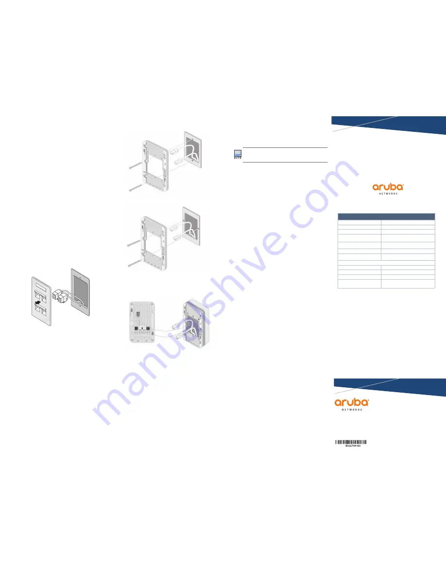
Installing the AP
The IAP-205H is designed to mount into a variety of electrical gang boxes.
1. Remove the existing data wall plate (if applicable).
2. Remove any existing RJ-45 connectors (typically snap-in) or cut/remove the
UTP cable.
Figure 5
Removing Wall Plate (US Single Gang Outlet Box Shown)
3. Use a short Ethernet cable (sold separately) to connect the E0 port to an RJ45
connector or crimp an RJ-45 plug (not supplied) on the cable and insert in the
E0 port. Do the same for the PT port, if used.
4. Align the mounting holes of the IAP-205H mounting bracket with mounting
holes in the gang box, as shown in
Figure 6
and
Figure 7
. For worldwide
single gang outlet box, the mounting bracket has two sets of mounting holes
to meet the individual installation position requirement. See
Figure 7
for
details.
The applicable standards for the wall boxes are:
IEC 60670-1, GB17466, BS4662 and DIN49073 for Worldwide
ANSI/NEMA OS 1 and OS 2 for US
5. Insert the two included machine screws and tighten them to secure the
mounting bracket.
Figure 6
Bracket to Gang Box (US Single Gang Outlet Box Shown)
Figure 7
Bracket to Gang Box (Worldwide Single Gang Outlet Box Shown)
6. Connect cables to the back of the AP.
7. Align the mounting slots on the back of the AP with the corresponding
mounting posts on the wall mount as shown in
Figure 8
.
8. Push the AP against the posts and downward until the posts engage the slots
at the top of the slots.
Figure 8
Attaching AP to Wall Mount
9. Once the AP is fastened onto the wall mount, insert the T8H Torx security
screw into the hole located on the upper-right edge of the wall mount and
tighten.
10. If not using PoE, connect the AC-DC power adapter (sold separately) to the
DC power socket located on the bottom of the IAP-205H.
Verifying Post-Installation Connectivity
The System Status LED on the AP can be used to verify that the AP is receiving
power and initializing successfully (see
Figure 1
). Refer to the
Aruba Instant
Quick Start Guide
for further details on verifying post-installation network
connectivity.
Product Specifications
Electrical
Ethernet:
4x 10/100/1000 Base-T auto-sensing Ethernet RJ-45 interface (E0-E3)
2x passive RJ-45 Pass-Through interface (E0/PT and PT)
MDI/MDX
IEEE 802.3 (10Base-T), IEEE 802.3u (100Base-T). IEEE 802.3ab
(1000Base-T)
Power over Ethernet (IEEE 802.3af and 802.3at compliant), 48VDC
(nominal) and 56VDC (maximum)/350mA (see
Figure 4
for pin
configuration)
Power:
48VDC power interface, supports powering through an AC-to-DC power
adapter
PoE support on Ethernet ports: 802.3af-compliant PoE sourcing device
Environmental
Operating:
Temperature: 0° C to +50° C (+32° F to +122° F)
Humidity: 5% to 95% non-condensing
Storage and transportation:
-Temperature: -40° C to +70° C (-40° F to +158°)
For additional specifications on this product, please refer to the data sheet. The
data sheet can be found at
www.arubanetworks.com
.
If a power adapter other than the one provided by Aruba is used in US or
Canada, it should be NRTL Listed, with an output rated 48VDC, minimum
0.75A, marked “LPS” and “Class 2”, and suitable for plugging into a
standard power receptacle in the US and Canada.


