Aruba AP-203R Installation Manual Download Page 6

6

Aruba 203R Series Wireless Access Point  | Installation Guide

the back panel of this device. 

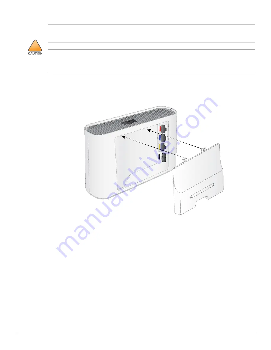
Use the steps below to install the rear snap on cover.
1. Ensure that the power and Ethernet cable(s) are plugged into the back of the access point.
2. Align the tabs on the snap-on cover with the corresponding slot on the back of the access point, then press 

the cover until it snaps into place. See 

Figure 5

.

Figure 5  

Snap on Cover

Software

For instructions on choosing operating modes and initial software configuration, refer to the Access Point 

Software Quick Start Guide. 

Verifying Post-Installation Connectivity

The integrated LED on the access point can be used to verify that the access point access point is receiving power 

and initializing successfully (see 

Table 1

-4

). Refer to the Access Point Software Quick Start Guide for further 

details on verifying post-installation network connectivity.

Electrical and Environmental Specifications

For additional specifications on this product, please refer to the product data sheet at 

www.arubanetworks.com/safety_addendum.

!

All Aruba access points should be professionally installed by an Aruba-Certified Mobility Professional (ACMP). 

The installer is responsible for ensuring that grounding is available and meets applicable national and electrical 

codes. Failure to properly install this product may result in physical injury and/or damage to property.

Tous les points d'accès Aruba doivent impérativement être installés par un professionnel agréé. Ce dernier doit 

s'assurer que l'appareil est mis à la terre et que le circuit de mise à la terre est conforme aux codes électriques 

nationaux en vigueur. Le fait de ne pas installer correctement ce produit peut entraîner des blessures 

corporelles et / ou des dommages matériels.

E1

E2

E0

AC

Summary of Contents for AP-203R

Page 1: ...int IEEE 802 11a b g n ac operation as a wireless air monitor Compatibility with IEEE 802 3 at PoE Central management configuration Supports PoE in E0 port PoE out E2 port Support for selected USB per...

Page 2: ...or State Meaning Off Device is powered off Green solid Device is ready fully functional Green blinking1 Device is booting not ready Green flashing2 Device is ready uplink negotiated at suboptimal spee...

Page 3: ...that can be selected in the system management software Default mode Refer to Table 1Tables 1 3 Off mode LEDs are off Blink mode LEDs blink green Figure 2 AP 303H rear view Color State Meaning Off Meet...

Page 4: ...w Energy BLE dongles When active the USB port can supply up to 5W 1A to a connected device Push Button The push button located on the bottom of the device can be used to reset the access point to fact...

Page 5: ...ing known RF absorbers reflectors and interference sources while in the field during the installation phase is critical Make sure that these sources are taken into consideration when you attach an acc...

Page 6: ...s Point Software Quick Start Guide for further details on verifying post installation network connectivity Electrical and Environmental Specifications For additional specifications on this product ple...

Page 7: ...of operation and may be subject to forfeiture 47 CFR 1 80 The network administrator s is are responsible for ensuring that this device operates in accordance with local regional laws of the host doma...

Page 8: ...strie Canada L utilisation de ce p riph rique est soumise aux deux conditions suivantes 1 ce p riph rique ne doit pas provoquer d interf rences et 2 ce p riph rique doit accepter toute interf rence y...

Page 9: ...ce code send a check or money order in the amount of US 10 00 to Hewlett Packard Enterprise Company Attn General Counsel 3000 Hanover Street Palo Alto CA 94304 USA Warranty This hardware product is pr...

Reviews: