46
SERVICE
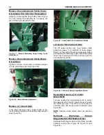
Figure 92 - Sprocket Alignment.
R
EPLACEMENT
O
F
W
ORN
O
R
D
AMAGED
H
AMMERS
Hammers must be replaced in pairs to maintain
proper balance. This is accomplished by replacing
the hammers opposite of each other (180 degrees
apart) using a matched pair.
R
EVERSING
T
HE
H
AMMERS
CAUTION: MAKE SURE THE HAMMER-
MILL
HAS
STOPPED
ROTATING
BEFORE THE HAMMERMILL DOOR IS
OPENED.
SHUT
THE
TRACTOR
IGNITION OFF AND PLACE THE KEY IN
YOUR POCKET. SAFELY DISENGAGE
ALL DRIVES.
There are four rows of hammers in the rotor
assembly with a total of 72 hammers on a 20 inch
hammermill. (See Figure 93) The hammers are
reversible, but make sure to always replace the
hammers and spacers in the exact sequence in
which they were removed. This will preserve the
balance of these specially matched units. All four
corners can be used on each hammer.
Figure 93 - Proper Hammer Spacing For 72 Hammers
(20 Inch Hammermill).
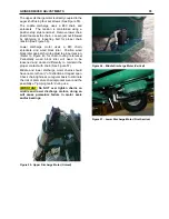
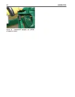
To remove the hammers, remove the bolts from the
side of the mill and round plate. (See Figure 94 and
Figure 95.) Remove the pins from each end of the
rod and pull the rods outward making sure the
hammers are put back in the same place from
which they were removed.
Figure 94 - Hammer Removal Inside Hammermill,
Hole To Remove Hammermill Rods (Shields
Removed For Clarity).
Figure 95 - Hammermill Removal Hole, Plate To Be
Removed (Shields Removed For Clarity).
M
AIN
D
RIVE
B
ELT
R
EPLACEMENT
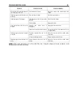
To remove the drive belts, loosen the bolts. (See
Figure 96, Detail B and C.) To relieve the belt
tension, loosen the bolts. (See Figure 82, Detail A.)
After the belts are no longer tensioned, remove the
belts and replace them with the new set and
continue as described in GRINDER MIXER
ADJUSTMENTS - Main Drive Belts. Make sure to
align the pulley and the sheave.
Summary of Contents for CATTLEMAXX 6105
Page 7: ...TABLE OF CONTENTS 5 ...
Page 14: ...12 INTRODUCTION Figure 5a Safety Decals ...
Page 22: ...20 PREPAIRING THE GINDER MIXER FOR OPERATION Figure 15 PTO Support ...
Page 27: ...OPERATION OF GRINDER MIXER 25 cleaned out Keep all bystanders away from the machine ...
Page 42: ...40 LUBRICATION Figure 70 Hammermill engaging pin shields removed for clarity ...
Page 49: ...SERVICE 47 Figure 96 Belt Removal Shields Removed For Clarity B C ...
Page 78: ...76 OPERATION OF CATTLEMAXX Figure 143 Hopper Inspection Window ...


