


GRINDER MIXER ADJUSTMENTS
37
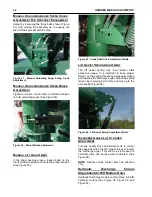
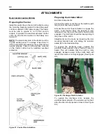
Figure 61 - Swivel Stop.
S
WIVEL
S
TOP
A
DJUSTMENT
Adjust the bracket so it makes contact before the
unloading auger contacts the tank.
O
PEN
A
ND
C
LOSED
H
YDRAULICS
As the standard, this machine is equipped for
tractor “Open Center” hydraulic operation.
If the operation of the auger feeder is to be with a
tractor that is equipped with a “Closed Center”
hydraulic system, revision to the plumbing at the
control valve bypass should be made. Refer to the
tractor operator’s manual or consult your local
tractor dealer to make sure which system the tractor
is equipped with. (See Figure 62)
To convert to “Closed Center” hydraulic system,
revise as shown. (See Figure 62) If the system has
two control valves for auger feeder and roll feed,
change only the roll feed flow control valve.
When
revised for “Closed Center” operation, do not
use on a
tractor with “Open Center”
.
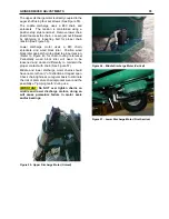
Figure 62 - Open And Closed Hydraulic Systems.
C
ONVERTING
T
O
C
LOSED
C
ENTER
H
YDRAULICS
To convert the hydraulic system to “Closed Center”
perform the following: (See Figure 62)
1. At the control valve upper right corner,
disconnect the hydraulic hose from the motor.
2. Disconnect the hydraulic hose to tractor from
the tee and elbow then remove the nipple.
3. Install the plugs in the valve and tee where the
nipple was removed.
4. Connect the hydraulic hoses to the tee and
elbow.
5. Tie the hoses together for additional support.
6. If equipped with hydraulic roll feed, do not
change the control valve for auger feed,
change it for the roll feed.
P
OSITIONING
T
HE
U
NLOADING
A
UGER
T
O
T
HE
O
PPOSITE
S
IDE
O
F
T
HE
M
ACHINE
CAUTION: BEFORE REPOSITIONING
THE
UNLOADING
AUGER
TO
OPPOSITE SIDE OF THE MACHINE,
MAKE SURE THERE IS ENOUGH
CLEARANCE
FROM
ALL
OBSTRUCTIONS STRAIGHT UP AND TO
THE REAR AND SIDES OF MIXER TANK
THE
SAME
LENGTH
AS
THE
UNLOADING AUGER.
STEP 1
– (See Figure 63) Lift the unloading auger
until the 5/8 inch hole in the lift lever is aligned with
the 5/8 inch x 1 inch slot in the vertical cylinder
mount arm. Lock the unloading auger into position
with either a 5/8 inch bolt and nut or a 5/8 inch clevis
pin.
STEP 2
– (See Figure 63) Detach the rod end of the
cylinder from the ball joint on the lift lever. Retract
the cylinder until it is aligned with the cylinder re-
positioning hole and re-attach. Remove the locking
bolt and/or pin from the 5/8 inch hole.
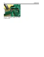
STEP 3
– (See Figure 64) Extend the cylinder until
the 5/8 inch hole is aligned with the other 5/8 inch x
1 inch slot. Lock the cylinder into position with a 5/8
inch bolt and nut or a 5/8 inch clevis pin.
Summary of Contents for CATTLEMAXX 6105
Page 7: ...TABLE OF CONTENTS 5 ...
Page 14: ...12 INTRODUCTION Figure 5a Safety Decals ...
Page 22: ...20 PREPAIRING THE GINDER MIXER FOR OPERATION Figure 15 PTO Support ...
Page 27: ...OPERATION OF GRINDER MIXER 25 cleaned out Keep all bystanders away from the machine ...
Page 42: ...40 LUBRICATION Figure 70 Hammermill engaging pin shields removed for clarity ...
Page 49: ...SERVICE 47 Figure 96 Belt Removal Shields Removed For Clarity B C ...
Page 78: ...76 OPERATION OF CATTLEMAXX Figure 143 Hopper Inspection Window ...


