


HARVESTER OVERVIEW
15
HARVESTER OVERVIEW
This manual has been prepared to familiarize the owner/operator with the proper assembly, operation, adjustment,
service, and lubrication of the harvester. Take adequate time to better understand the efficient operation and care of your
harvester.
Whenever the term(s) “left-hand” and “right-hand” are used, it should be understood that this means you are standing
behind the harvester and facing the direction of forward travel.
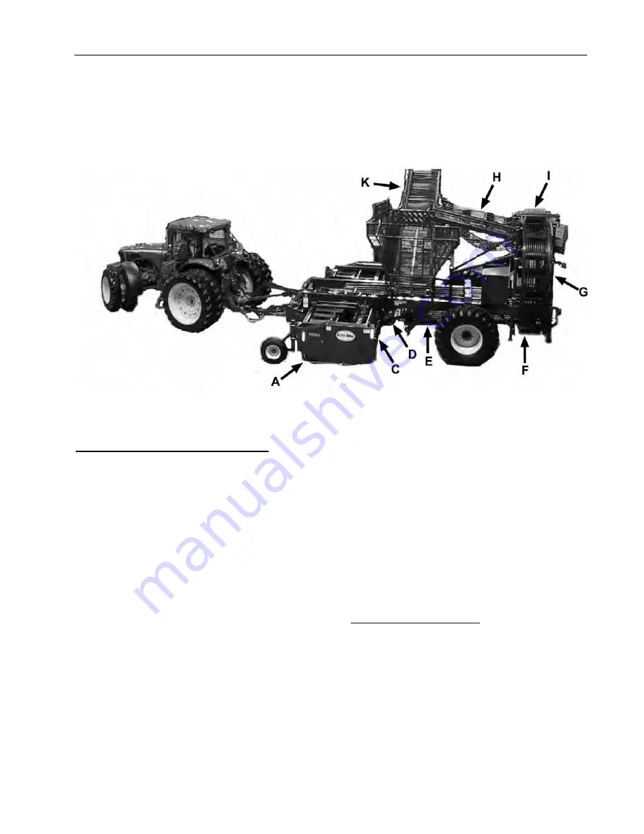
Figure 7 - 6812A Sugar Beet Harvester
B
EET
F
LOW
H
ARVESTING
S
EQUENCE
The lifter wheels of the header (A) penetrate the soil and
lift the beets upward out of the ground.
The revolving rubber paddles (B – Not Seen) located
above and slightly rear of the lifter push the beets
towards the header conveyor rollers. The paddles also
serve to clean the beets by removing excess dirt from
the beets surface.
The header conveyor rollers (C) also serve to remove
dirt from the beets as well as transfer the beets to the
main harvester grabrollers. Depending upon the
owner/operators preference, the first header roller can
be either a star or smooth roller to match soil conditions.
The diverter roller is smooth and acts as a grabroll with
the rear header conveyor roll.
A short conveyor (D) located to the rear of the header
serves to transfer the beets from the header to the main
harvester grabrollers (E). This short conveyor is secured
to the header and is allowed to free float on the main
harvester frame to allow for orientation changes
between the header and main harvester frame.
The main harvester grabroller bed consists of four spiral
grab rollers paired with four smooth rollers that strip dirt,
soil, and trash from the beets as they are transferred to
the wheel elevator (F).
The wheel elevator, set slightly lower than the main
harvester grabroller bed, receives and then carries the
beets to the top of the harvester. A retainer (G) holds
the beets in the wheel elevator until they reach the top
where the beets fall onto the holding tank conveyor (H).
A stripper (I) clears the wheel elevator of any rocks or
beets that may become wedged between the wheel
elevator rods.
The transfer conveyor transports the beets from the
wheel elevator to the holding tank.
The offloading conveyor (K) also serves as the bottom
of the holding tank. The offloading conveyor extends up
and outward to facilitate the offloading of the beets to a
truck or other appropriate vehicle.
H
ARVESTER
S
TRUCTURE
The basic structure of the harvester is its frame. From
the frame all of the major assemblies such as the
header, holding tank, wheels, and conveyors are
attached. In its operational configuration, (i.e. the
header attached and the holding tank empty) the
harvester has a total weight of approximately ranging
from 30,000 lbs [13,607 kg] for the 6 row 28/30 to
37,000 lbs [16,782 kg] for the 12 row 22.
Summary of Contents for 6812A
Page 12: ...10 SAFETY DECALS ...
Page 13: ...SAFETY DECALS 11 ...
Page 14: ...12 SAFETY DECALS Figure 6 Header Safety Decals ...
Page 15: ...SAFETY DECALS 13 ...
Page 16: ...14 SAFETY DECALS ...
Page 41: ...TROUBLE SHOOTING GUIDE 39 Figure 76 Tractor Harvester Hydraulic System ...
Page 42: ...40 TROUBLE SHOOTING GUIDE Figure 77 Harvester Self Contained Hydraulic System ...
Page 62: ...NOTES ...


