RIO-2015PG Hardware Guide
5
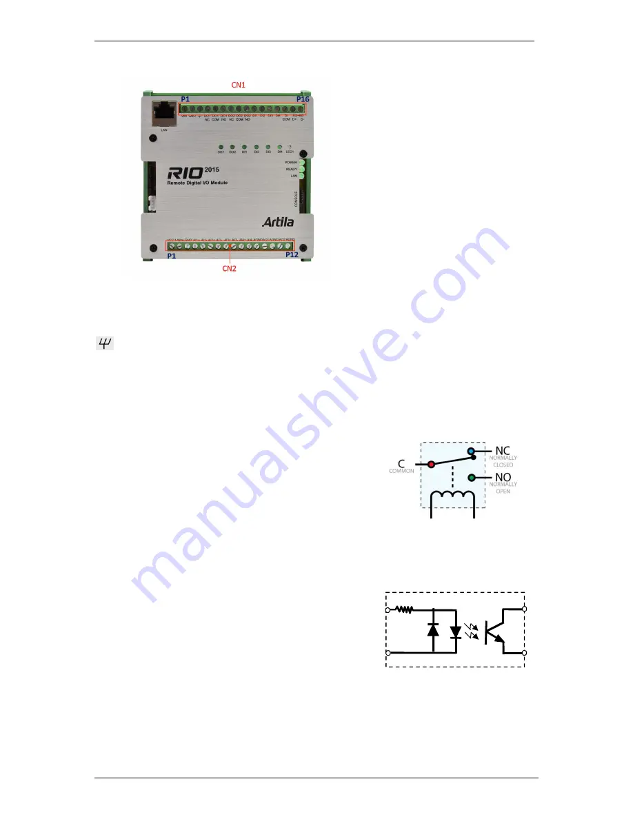
3. Pin Assignment and Definition
3.1 Power In: (CN1: P1~P3)
Vin (P1):
DC power + in
Gnd (P2):
power ground
(P3):
Chassis ground
Connecting 9~48VDC power to Vin and Gnd. If the power is properly supplied, the Power LED will
keep solid green color and a beep will be heard. The chassis ground is to connected to chassis or
earth ground if needed.
3.2 Relay Output (CN1: P4~P9)
DO1_NC (P4):
Relay one normal close
DO1_COM (P5):
Relay one common
DO1_NO (P6):
Relay one normal open
DO2_NC (P7):
Relay two normal close
DO2_COM (P8):
Relay two common
DO2_NO (P9):
Relay two normal open
3.3 Isolated Digital Input (CN1: P10~P14)
DI1 (P10):
Digital input 1
DI2 (P11):
Digital input 2
DI3 (P12):
Digital input 3
DI4 (P13):
Digital input 4
DI_COM (P14):
Common pin of DI1~DI4
3.4 Isolated RS-485 (CN1: P15~P16)
D+ (P15):
Data+
D- (P16):
Data-
DI1~4
DI_COM


