background image

DrillSaw Highspeed 200™ 

User’s Guide


DFU-0225-2 Rev. 0 

Page 19 of 58 

3.2 

Motor AR-200M 

Table 11 

Motor AR-200M Specifications 

Diameter 

26.3 mm (1.04 in.) 

Length 

 96 mm (3.78 in.)  

Weight 

0.42 kg (0.93 lbs.)  

Speed 

300-15,000 rpm  

Torque 

7 Ncm 

Length in Cable 

3.5 m (137.8 in.) 

Cleaning 

Refer to Section 6.0 Cleaning and Disinfecting 

Sterilization 

Refer to Section 7.0 Sterilization 

Mode of Operation  

Non-continuous 

Applied part type 

Type BF  

Operation Mode 

30sec ON, 60sec OFF (max. 4 repetitions) 

3.3 

Motor AR-200M-ISO 

Table 12 

Motor AR-200M-ISO Specifications 

Diameter 

23 mm (0.91 in.) 

Length 

112 mm (4.41 in.) 

Weight 

0.38 kg (0.84 lbs.) 

Speed 

300-40,000 rpm 

Torque 

7 Ncm 

Length in Cable 

3.5 m (137.8 in.) 

Cleaning 

Refer to Section 6.0 Cleaning and Disinfecting 

Sterilization 

Refer to Section 7.0 Sterilization 

Mode of Operation  

Non-continuous 

Applied part type 

Type BF  

Operation Mode 

30 sec ON, 60 sec OFF (max. 4 repetitions) 

3.4 

Foot Control Unit 

Table 13 

Foot Control Unit  (S-N1) Specifications 

Width 

207 mm (8.15 in.) 

Height 

45 mm (1.77 in.) 

Depth 

198 mm (7.79 in.) 

Weight 

1.15 kg (2.2 lbs.) 

Cable length 

3.5 m (137.8 in.) 

Cleaning 

Surface cleaning with mild detergent 

Sterilization 

No 

Protection 

IPX8, 1 m depth of immersion ,  

1 hour (water-tight in accordance with IEC 60529) 


Summary of Contents for Highspeed 200

Page 1: ...ating personnel must read this User s Guide thoroughly prior to using this system and follow all safety warnings cautions and precautions Arthrex Inc 1370 Creekside Blvd Naples FL 34108 1945 USA Toll Free 1 800 934 4404 www arthrex com Arthrex GmbH Erwin Hielscher Strasse 9 81249 München Germany Tel 49 89 909005 0 www arthrex de DFU 0225 2 Revision 0 September 2018 2016 Arthrex Inc All rights rese...

Page 2: ...This page intentionally left blank ...

Page 3: ... 3 AR 200C Console Main Screen and Iconography 12 2 5 4 Foot Control Unit S N1 13 2 5 5 AR 200M AR 200M ISO Motors with Cable 15 2 5 6 AR 200SP Spray Clip 17 3 3 0 0 Technical Specifications 18 3 1 Console AR 200C 18 3 2 Motor AR 200M 19 3 3 Motor AR 200M ISO 19 3 4 Foot Control Unit 19 3 5 Safety EMC and Regulatory Requirements 20 4 4 0 0 Setup 21 4 1 How to Set Up the Console 21 4 2 AC Power Saf...

Page 4: ...mber 35 5 5 0 0 Operation and Frequently Used Functions 36 5 1 Changing the Program 37 5 2 Changing the Speed 37 5 3 Changing the Torque 38 5 4 Changing the Coolant Flow 38 5 5 Changing Settings with the Foot Control Unit 38 5 6 System Shutdown 39 5 7 Backup System 39 5 8 Infrequently Used Functions 39 6 6 0 0 Cleaning and Disinfecting 40 6 1 Preliminary Cleaning 40 6 2 Console AR 200C 40 6 3 Moto...

Page 5: ... N1 13 Figure 5 AR 200M Motor with AR 300 Attachment Coupling 15 Figure 6 AR 200M ISO Motor with ISO Saw Attachment Coupling 16 Figure 7 AR 200SP Spray Clip 17 Figure 8 Set up the AR 200 23 Figure 9 Connecting and removing an attachment 25 Figure 10 Irrigation Pump Tubing Setup 26 Figure 11 Connection of AR 200SP Spray Clip to the Motor AR 200M 28 Figure 12 Connection of AR 200H handle to the AR 2...

Page 6: ...necting and removing an attachment 25 Table 16 Irrigation Pump Tubing Configuration 26 Table 17 One Piece Tubing Configuration 28 Table 18 AR 200H handle connection to AR 200M motor 29 Table 19 Calling Up the Settings Screens 30 Table 20 Factory Settings AR 200C 34 Table 21 Troubleshooting Faults Causes and Solutions 49 Table 22 Guidance and Manufacturer s Declaration Electromagnetic Emissions 54 ...

Page 7: ...ian This device should not be used by untrained personnel or used for indications other than those described in this User s Guide 3 The device is intended to apply mechanical force rotational energy to the patient 4 Check the console the motor and the foot control with cables for damage and loose parts before each use Correct any faults or refer to an authorized Arthrex service partner Do not oper...

Page 8: ...ng gases such as nitrous oxide oxygen or endogenous gases All oxygen connections must be leak free for the duration of the surgical procedure 22 After autoclaving the accessory devices are VERY HOT Handle with care to avoid burns 23 The console the motors with cable and the footswitch are not suitable for use in potentially explosive atmospheres or with potentially explosive mixtures of anesthetic...

Page 9: ...cessory device can damage the device Before connecting the cable ensure the receptacles are clean and dry 11 Always comply with the instructions issued by the manufacturer of the cleaning disinfectant regarding concentration exposure times temperature and material compatibility 12 NEVER allow the console receptacles to have any contact with liquids If there is dust or moisture on the receptacles r...

Page 10: ...uctions Caution Federal law restricts this device to sale by or on the order of a physician On Off push push Fragile handle with care Caution Precaution This side up Keep dry Temperature limits for storage and transport Electrical hazard dangerous voltages are present Never attempt to repair the equipment Only trained service personnel may remove the cover or obtain access to system components Atm...

Page 11: ...3 42 EEC Catalog number Serial number Quantity Authorized representative in the European Community Do not use if package is damaged Non ionizing radiation x Square brackets that enclose a letter number or lower case Roman numeral reference a callout on a line drawing The section for Product Features includes line drawings of products associated with the DrillSaw Highspeed 200 Each line drawing has...

Page 12: ...not reported within seven business days of receiving the device Refer also to our General Terms of Business All defective products will be repaired or replaced at the discretion of Arthrex at no charge The warranty does not cover damage caused by unlawful use or improper handling of a product The warranty is not valid if modifications are made to the product or repairs are carried out outside of A...

Page 13: ...d on the physician target group Patient Population Whoever needs an orthopedic surgical intervention defined in the intended use demanding the use of a power tool Conditions of Use The system is used in an operating room The motors with connected attachments are intended to be used in the sterile field The console is located in the operating room close to the operation field unsterile and shall st...

Page 14: ...n Tubing Set 3 pieces CE0481 OEM04005900 Stand CE0086 OEM06177800 Motor support CE0086 WH013437000 01 Power Cord with a European Plug CE0086 WH028214000 01 Power Cord with a US Plug CE0086 The AR 200M ISO includes AR 200M ISO Motor with cable for ISO saw attachments CE0086 OEM04006800 Locking Pin CE0086 Accessories for AR 200M ISO motor 10100801 AR 200 ISO SAW S 8R RECIPROCATING CE0297 10100802 AR...

Page 15: ...0M motor are listed in Table 26 Other optional accessories OEM06290600 AR 200 CLIPS 5 PIECES OEM06352200 AR 200 FUSE 250V T1 6AH OEM07149200 AR 200 CLEANING ADAPTER FOR SPRAY CLIP OEM01525000 AR 200 SILICONE TUBING FOR CLEANING ADAPTER 10 PIECES OEM04013500 AR 200 STERILIZATION CASSETTE CE OEM043641006 Irrigation Tubing Set 6 pieces CE0481 ...

Page 16: ...llout system to identify the main elements of the console s front panel which are listed and labeled in Table 1 These callouts are referenced throughout this User s Guide Figure 1 Front Panel of Console Table 1 Front Panel Elements 1 Shift buttons 2 Operator display 3 PLUS MINUS buttons 4 Motor connecting socket 5 Pump arm OPEN 6 Pump arm 7 Stand holder ...

Page 17: ... identify the main elements of the console s rear panel which are listed and labeled in Table 2 These callouts are referenced throughout this User s Guide Figure 2 Rear Panel of Console Table 2 Rear Panel Elements 8 Connecting socket for foot control 9 AC mains power input plug 10 Main power input Fuse holder 250V T1 6AH 11 AC Mains power ON OFF ...

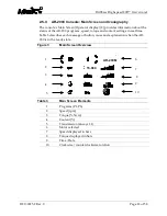
Page 18: ... torque and coolant settings in real time Table 3 describes each message or button cause and explanation when the AR 200 is in the ready state Figure 3 Main Screen Overview Table 3 Main Screen Elements 1 Programs P1 P6 2 Speed rpm 3 Torque Ncm 4 Coolant 5 Transmission always 1 1 6 Motor selected 7 Speed displayed in bars 8 Torque displayed in bars 9 Time Date 10 Clockwise counterclockwise rotation...

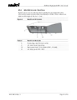
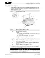
Page 19: ... the Handle into the two holes of the Foot Control Unit 2 Insert the Handle until the stop is reached Detach Pull out the handle until completely removed 13 Green Pump on off 14 Grey Start motor pedal variable or ON OFF factory setting variable 15 Yellow Change motor direction clockwise counterclockwise rotation 16 Orange Change program programs 1 to 6 When counterclockwise rotation is used the mo...

Page 20: ...s tilted outwards at a 30 angle W A R N I N G Zone G also known as an enclosed medical gas system does not necessarily include areas enclosed around all sides in which explosive mixtures are continuously or temporarily generated directed or used in small quantities Do not disconnect the plug of the foot pedal unit by pulling on the cable Remove the foot control plug by grasping and pulling on the ...

Page 21: ...ed to all AR 300 attachments except the AR 300CA Offset Cannulation Adapter The motors with cable must not be disassembled The motors with cable must not be lubricated during their lifetime Please note that at low speeds it is more difficult to determine that the motor is running The motors must be used in compliance with the operation mode Please refer to the User s Guide DFU 0223 XX for more inf...

Page 22: ... that are listed in this User s Guide as official DrillSaw Highspeed 200 accessories These ISO saw attachments provide their own User s Guide Coupling system according to ISO 3964 DIN 13940 Please refer to the device specific User s Guide and safety notes for more information about the ISO saw attachments that can be connected to the AR 200M ISO motor To prevent the ISO saw attachments from turnin...

Page 23: ... Clip can be attached to the AR 200M motor with cable and leads the irrigation fluid to the tip of the connected burr The Spray Clip is not intended to be used with the motor AR 200M ISO since the ISO saw attachments have their own spray rod attached The irrigation tubing set can be connected on the proximal side 3 of the Spray Clip The fluid pump can be activated deactivated on the AR 200C consol...

Page 24: ...Ambient Conditions for Operation Temperature 10 to 40 C 50 to 104 F Relative Humidity 15 to 80 relative non condensing Table 10 Ambient Conditions for Storage in shipping packaging Temperature 40 to 70 C 40 to 158 F Relative Humidity 8 to 80 relative non condensing Atmospheric Pressure 700 hPa 1060 hPa In the event of a power failure or if the AR 200C is switched off or when switching between prog...

Page 25: ... AR 200M ISO Specifications Diameter 23 mm 0 91 in Length 112 mm 4 41 in Weight 0 38 kg 0 84 lbs Speed 300 40 000 rpm Torque 7 Ncm Length in Cable 3 5 m 137 8 in Cleaning Refer to Section 6 0 Cleaning and Disinfecting Sterilization Refer to Section 7 0 Sterilization Mode of Operation Non continuous Applied part type Type BF Operation Mode 30 sec ON 60 sec OFF max 4 repetitions 3 4 Foot Control Uni...

Page 26: ...I exempt EU class Class IIa Health Canada Class Class 2 Safety Certifications Domestic Certification ANSI AAMI ES60601 1 2005 C2 A2 Canadian Certification CSA C22 2 No 60601 1 2008 EU Certification IEC 60601 1 2005 A1 2012 EMC Certifications EMC Certification EN 60601 1 2 2015 09 Safety Certification Marking UL CE Classification MDD 93 42 EEC Annex IX Rule 9 Class IIa Refer to section 14 for furth...

Page 27: ...200C is being used Contact your Arthrex representative for further information Avoid positioning the console so that it is difficult to disconnect the coupler or plug from the mains supply To prevent electrical shock do not use extension cords or two prong three prong adaptors The third conductor in the power supply cord is only a functional earth If required by local codes connect the console to ...

Page 28: ...isconnect the device from the AC mains power supply 2 Open the fuse tray in the AC inlet 10 by pinching the tabs and pulling outward 3 Replace the fuses with 2 x 250V T1 6AH Line Fuses as noted on the rear panel 4 Push the fuse holder back into the AC inlet 5 Ensure that the fuse holder is fully seated and that the tabs snap back Always use fuses with the correct values to avoid allowing overcurre...

Page 29: ...s are connected to 4 Consult the manufacturer or field service technician for the receiving device for guidance 4 5 Basic Setup Procedure for the AR 200 Place the AR 200C on a flat dry and stable surface Figure 8 Set up the AR 200 Table 14 Set up the AR 200 a Connect the receiver end of the power cord for the AR 200C into the AC mains power socket 14 and connect the plug end into the facility AC m...

Page 30: ...e system Contact your Arthrex representative for a complete list of accessories DO NOT modify any accessory Failure to comply may result in injury to the patient and or operating room staff W A R N I N G Do not use in the presence of flammable anesthetics or oxidizing gases such as nitrous oxide oxygen or endogenous gases All oxygen connections must be leak free for the duration of the surgical pr...

Page 31: ...to the AR 200M motor Figure 9 Connecting and removing an attachment Table 15 Connecting and removing an attachment a To Insert the attachment Step 1 Turn the motor chuck mechanism Step 2 Push the adaptor into the locking mechanism Step 3 Loosen the chuck mechanism Note For insertion only Steps 1 and 2 can be combined b To Remove the attachment Turn the motor chuck mechanism Pull out the adaptor a ...

Page 32: ... irrigation pump tubing a Open the Pump arm door b c d Insert the irrigation pump tubing e Close the pump arm door It is confirmed by physically hearing and feeling the latching mechanism The surface of the door is flush with the surface of the front panel Follow the sequences a e when removing the irrigation tubing The AR 200 is designed for use with physiological saline solution Use only suitabl...

Page 33: ... These irrigation pump tubing is disposable and must be discarded after each use Please note the expiration date and the relevant regulations for disposal of irrigation pump tubing Only use disposable irrigation pump tubing with undamaged packaging sealing W A R N I N G Never touch the pump motor while the pump arm door is open ...

Page 34: ... Spray Clip Figure 11 Connection of AR 200SP Spray Clip to the Motor AR 200M Table 17 One Piece Tubing Configuration a Attach the Spray Clip to the motor The Spray Clip groove matches with the coupling ring of the motor a Insert the tubing end onto the proximal rod end of the Spray Clip c If needed Fix the irrigation tubing in the clips of the motor cable a b c ...

Page 35: ...00H handle connection to AR 200M motor a Attach the handle to the AR 200M motor cable Pay attention to the orientation The arrow on the handle indicates the correct direction b Slide the handle up the motor until it reaches the coupling ring c The handle can also be used with the Spray Clip This configuration is shown with a drill attachment The AR 200H handle can only be used with the AR 200M mot...

Page 36: ...1 2 General settings are highlighted in Choose Settings Screen Confirm by pressing the PLUS button For a description of the general settings see chapter 4 12 3 AR 200 settings are highlighted in Choose Settings Screen Confirm by pressing the PLUS button For a description of the AR 200 settings see chapter 4 13 Exit Highlight EXIT button and press PLUS or MINUS Enter highlighted console and PLUS bu...

Page 37: ... back to the Choose Settings Screen The LED buttons and the display of the AR 200 must light up fully before use 4 12 General Settings Press shift button or 1 to select the desired menu Press the PLUS MINUS button 3 to set the menu functions The selected functions light up in green To exit the general settings select Return with shift button Confirm with the PLUS MINUS button 4 4 1 12 2 1 1 Changi...

Page 38: ...he Time 1 Select function Time 2 Activate time settings 3 Select time format am pm 24h select hours minutes or seconds or exit the time settings 4 Adjust the settings for time format hours minutes and seconds 4 4 1 12 2 3 3 Changing the Contrast 1 Select function Contrast 2 Increase contrast 3 Decrease contrast 4 4 1 12 2 4 4 Changing the Volume 1 Select function Volume 2 Increase volume ...

Page 39: ...se volume Mute 4 4 1 12 2 5 5 Reset Factory Setting 1 Select function Reset 2 Start reset countdown 3 3 The reset countdown can be interrupted within 5 seconds by pressing the MINUS button 4 4 1 12 2 6 6 Exit setting 1 Select function Exit 2 Confirm with PLUS or MINUS button 3 ...

Page 40: ...wise P3 3 000 100 100 disabled 1 1 clockwise P4 15 000 100 100 disabled 1 1 clockwise P5 15 000 100 100 disabled 1 1 clockwise P6 15 000 100 100 disabled 1 1 clockwise For AR 200M ISO motor with cable Program Speed rpm Torque Ncm Coolant supply volume Coolant Transmissio n ratio Motor direction P1 40 000 100 100 disabled 1 1 clockwise P2 40 000 100 100 disabled 1 1 clockwise P3 30 000 100 100 disa...

Page 41: ...ting Continuously variable motor control ON OFF motor runs either with 100 speed grey pedal 14 is pushed or 0 speed grey pedal 14 is not pushed 4 13 2 Show Hardware Software Production Date and Serial Number In the down left corner of the display 3 numbers can be seen mmi Front Board number mot Motor controller Board number cfg SD Card number Technical Support may request the software version of t...

Page 42: ...he desired menu Press the PLUS MINUS button to set the menu functions The selected functions light up in green When changing settings no separate confirmation is necessary W A R N I N G Check the console the motor and the foot control unit with cables for damage and loose parts before each use Correct any faults or refer to an authorized Arthrex service partner Do not operate the AR 200 if it is d...

Page 43: ...m press MINUS button 5 2 Changing the Speed When the safety speed 15 000 rpm for AR 200M 40 000 rpm for AR 200M ISO is reached an audible signal safety stop sounds Keeping PLUS MINUS depressed activates the repeat function and the values are continuously increased decreased 1 Select menu Speed 2 Increase speed press PLUS button 3 Decrease speed press MINUS button ...

Page 44: ...anging the Coolant Flow Adjustable range 0 100 By keeping PLUS MINUS depressed the values are continuously increased decreased 1 Select menu Coolant 2 Increase flow rate in 20 steps press PLUS button 3 Decrease flow rate in 20 steps press MINUS button 5 5 Changing Settings with the Foot Control Unit Changing the program Press the ORANGE button 16 to select programs 1 to 6 in ascending order Hold t...

Page 45: ...unning and the counterclockwise symbol flashes Before the motor starts running an audible warning signal is given 5 6 System Shutdown 1 Turn the power switch to the OFF position on the rear side of the console 2 Disconnect the power cord from the wall outlet 3 Disconnect the Spray Clip and irrigation pump tubing if applicable 4 Disconnect the motor with cable from the console 5 Disconnect the foot...

Page 46: ... used on each patient Note No assembly disassembly of these instruments is required unless stated on the labeling directions for use or literature assembly instructions LAI pertaining to cleaning disinfection and sterilization 1 Devices that require disassembly should be disassembled prior to cleaning 2 Remove dried on soil from devices especially in areas such as joints and crevices prior to wash...

Page 47: ...ng on the AR 200C console 6 3 Motor with Cable AR 200M AR 200M ISO and Spray Clip AR 200SP The motor with cable AR 200M AR 200M ISO is supplied non sterile After cleaning sterilize the motor Clean and disinfect the motor with cable immediately after every treatment The Spray Clip is provided non sterile The Spray Clip can be cleaned and sterilized with the suggested cleaning devices provided by Ar...

Page 48: ...ction of the device Machine Wash Parameters MINIMUM WASHING CYCLE PARAMETERS Phase Recirculation Time Temperature Detergent Cold Pre Wash 3 Minutes 68 9 F 20 5 C N A Cleaning Wash 10 Minutes 150 9 F 65 5 5 C Enzymatic or alkaline agent Rinse 1 3 Minutes 122 9 F 50 5 C N A Rinse 2 3 Minutes 122 9 F 50 5 C N A Thermal Disinfection Rinse 5 Minutes 194 9 F 90 5 C N A Drying 6 Minutes 239 F 115 C N A N...

Page 49: ...trol unit thoroughly under lukewarm water Always comply with the instructions issued by the manufacturer of the cleaning disinfectant regarding concentration exposure times temperature and material compatibility NEVER allow the foot control unit receptacles to have any contact with liquids If there is dust or moisture on the receptacles remove using dry compressed air ONLY dry connectors should be...

Page 50: ...ronic components and seals Liquid on the cable connector of the accessory device can damage the device Before connecting the cable ensure that the receptacles are clean and dry The control unit AR 200C and the foot control unit S N1 are not approved for sterilization 7 1 Motor with Cable AR 200M AR 200M ISO and Spray Clip AR 200SP Sterilize the motor with cable and the motor support and Spray Clip...

Page 51: ...nutes Pre vacuum Cycle 132 C 270 F 4 Minutes 20 to 30 Minutes 135 C 275 F 3 Minutes 16 Minutes STERILIZATION PARAMETERS FOR OUTSIDE THE USA ONLY Exposure Temperature Exposure Time Drying Time Gravity Displacement Steam Sterilization Cycle 132 C 135 C 18 Minutes 15 to 30 Minutes 270 F 275 F 121 C 250 F 30 Minutes 15 to 30 Minutes Pre vacuum Cycle 132 C 135 C 4 Minutes 20 to 30 Minutes 270 F 275 F W...

Page 52: ...pathy Agents It is outside the scope of this document to describe in detail the precautions that should be taken for Transmissible Spongiform Encephalopathy TSE Agents The agents for transmission of Creutzfeldt Jakob disease are believed to be resistant to normal disinfection and sterilization processes Therefore the normal processing methods of decontamination and sterilization as described above...

Page 53: ...efore each use Your authorized Arthrex service department is extremely knowledgeable about the Arthrex DrillSaw Highspeed 200 motors and or foot control unit and will provide a competent and efficient service Any services and or repairs carried out by any unauthorized repair facility may result in reduced performance of the instruments or instrument failure 8 1 Periodic Maintenance The product sho...

Page 54: ... the Arthrex Technical Support Hotline at 1 888 420 9393 Monday through Friday from 9 00 AM to 5 00 PM EST or at 49 89 90 90 05 8800 or techsupport arthrex de from 8 00 AM to 5 00 PM CET 9 1 Additional Technical Information Contact your Arthrex representative if you require more comprehensive technical information Other information will be provided upon request by Arthrex APPROVED SERVICE PERSONNE...

Page 55: ...Motor faulty Connect a functioning motor Shift buttons or PLUS MINUS buttons activated when switching on the device Release the activated button switch off the device and restart Electronics overheating Safety shutdown Switch off the device and allow to cool for at least 10 minutes then restart Electronics overloaded Switch off the device and restart Call service Switch off the device and restart ...

Page 56: ...one or more of the following to correct interference Reorient or relocate the receiving device Increase the distance between the devices Connect the device to an outlet on a different circuit than the other device s are connected to Consult the manufacturer or field service technician for the receiving device for assistance ...

Page 57: ...DrillSaw Highspeed 200 User s Guide DFU 0225 2 Rev 0 Page 51 of 58 11 Repair Policy Contact Arthrex for a return authorization number and instructions prior to returning the device ...

Page 58: ... is not a warranty document For all warranty information including disclaimers exclusions terms conditions and related provisions refer to the Arthrex U S Product Warranty section of the Arthrex Inc website found at www arthrex com whose provisions are incorporated herein by reference ...

Page 59: ...f WEEE in unsorted municipal waste The WEEE symbol on the product or its packaging indicates that this product must not be disposed of with other waste Instead it is your responsibility to dispose of your waste equipment by handing it over to a designated collection point for the recycling of Waste Electrical and Electronic Equipment The separate collection and recycling of your waste equipment at...

Page 60: ... Group 1 The DrillSaw Highspeed 200 uses RF energy only for its internal function Therefore its RF emissions are very low and not likely to cause any interference with nearby electronic equipment RF emissions CISPR 11 Class B The DrillSaw Highspeed 200 is suitable for use in all establishments other than domestic and those directly connected to the public low voltage power supply network that supp...

Page 61: ...that of a typical commercial or hospital environment Surge IEC 61000 4 5 1 kV line s to line s 2 kV line s to earth 1 kV line s to line s 2 kV line s to earth Mains power quality should be that of a typical commercial or hospital environment Voltage dips short interruptions and voltage variations on power supply input lines IEC 61000 4 11 5 Uτ 95 dip in Uτ for 0 5 1 250 cycle 70 Uτ 30 dip in Uτ fo...

Page 62: ... distance in meters m Field strengths from fixed RF transmitters as determined by an electromagnetic site survey a should be less than the compliance level in each frequency range b Interference may occur in the vicinity of equipment marked with the following symbol NOTE 1 At 80 MHz and 800 MHz the higher frequency range applies NOTE 2 These guidelines may not apply in all situations Electromagnet...

Page 63: ...huck 0 3 0 mm AR 300DK45 Drill Keyless Chuck 2 0 4 5 mm AR 300DJ Drill Jacobs Chuck 0 4 0 mm AR 300DAO 2 Drill Attachment Style AO AR 300DJH Drill Jacobs Chuck Hybrid 0 5 0 mm AR 300B Burr Attachment 2 35mm AR 300B 2 Drill Attachment 2 35mm AR 300RAO Reamer Attachment Style AO AR 300RJ Reamer Jacobs Chuck 0 4 0mm AR 300WD16 Wire Driver Attachment 0 6 1 6 mm AR 300PD24 Pin Driver Attachment 1 0 2 4...

Page 64: ...reekside Blvd Naples FL 34108 1945 USA www arthrex com Customer Service 1 800 934 4404 Toll Free Technical Support 1 888 420 9393 Monday through Friday 9 00 AM 5 00 PM EST Arthrex GmbH Erwin Hielscher Strasse 9 81249 München Germany Tel 49 89 909005 0 www arthrex de All rights reserved ...

Reviews: