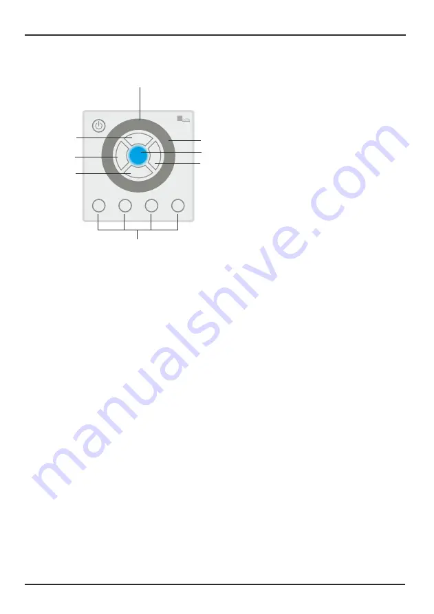
1. Power key
Used to power on/off DLC-4.
7. Touch toggle
Used to adjust color, brightness and speed, and select built-in programs.
5. B key
(brightness)
Used to adjust brightness.
2. C key
(color)
Used to select color.
3. P key
(program)
Used to select Built-in program.
4. S key
(speed)
Used to adjust speed.
6. Output Indicator
Used to display the current output.
8. Figure keys (1~4)
Used to record scene and color, as well as set fadetime.
Figure 1
DLC-4 features one group DMX OUT with 4-pin terminal connector, one group
POWER IN & PWM OUT with 6-pin terminal connector. The configuration of
the terminal is as the following(figure 2):
1. (4-pin terminal) LINK IN
2. (4-pin terminal) DMX OUT
3. (6-pin terminal) PWM OUT & POWER-IN
1. (4-pin terminal) LINK OUT
Page 2
DLC-4 User Instruction
Page 3
DLC-4 User Instruction
Control Panel and Functions
Rear Panel View
Installation
Connect the POWER IN to a 12-24V DC Powersupply
and connect the PWM OUT to the RGB fixture(s)
max. load is 6A;
at 12V load max. 72W (3x 24W)
at 24V load max. 144W (3x 48W)
If needed more than 6A, connect the DMX-OUT to the
next DMX-dimmerpack(s) LED-Domotion 3 (A9915015)
Note:
The DLC-4 will cover and can be
mounted on a European wallbox.
Mounting on a wallbox:
1. Remove screws &
A
B
2. Remove the cover and mount the controller.
3. Mount the cover with screws &
A
B
60mm
C
P
B
S
1
2
3
4
DLC-4
Domotion DLC-4
DMX-out
12-24V DC
RGB Light Fixtures (max.6A)
RGB Light Fixtures
(Domotion)
DMX Dimmerpack
12-24V DC
Powersupply
Figure 2
LINK IN
DMX OUT
LINK OUT
DC IN
PWM OUT
Made in P.R.C.
24-005-1396-01
GND
D-
D+
V+
GND
D-
D+
V+
GND
D-
D+
B
V+
G
R
GND
V in+
V+
1
2
3
4
C
P
B
S
1
2
3
4
DLC-4
2
3
4
1
5
6
7
8
Dimensions in mm
85x85
30
15.5
wallbox
wall
Link-
IN
DMX-
OUT
DC-IN
PWM-out
Link-
OUT
Remove screws A & B for mounting on a wallbox
A
B


