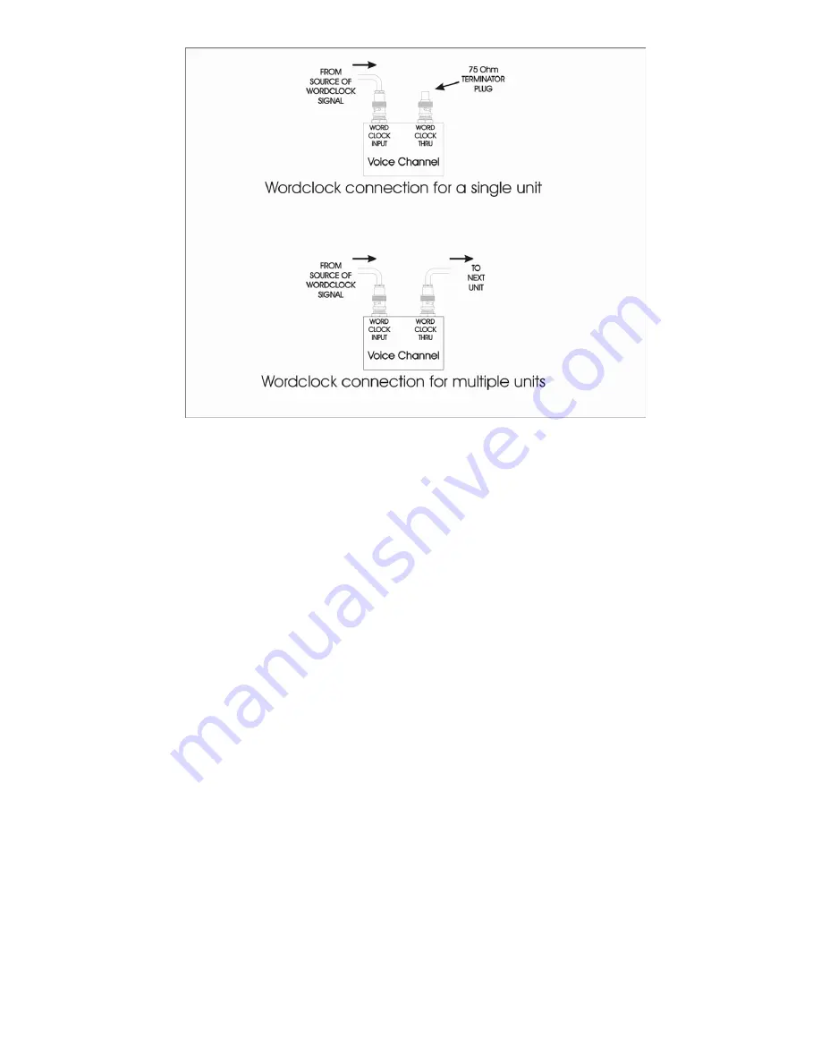
FIGURE 7 – Wordclock Termination
ADAT Input Jack
The optical ADAT input allows the Voice Channel™ A/D converter to synchronize to systems using ADAT
optical connections. The Voice Channel™ inserts its output in channels 1 and 2 of the ADAT stream while
passing through channels 3 thru 8. Select ADAT/16 or ADAT/24 with the Sample Rate control on the front
panel to enable this mode.
Optical Output Jack
The OPTICAL OUTPUT jack works in conjunction with the front panel OPTICAL OUTPUT switch, to output
either an ADAT formatted signal or a TOS formatted signal. The front panel SAMPLE RATE/DITHER control
sets the sample rate, dither, and sync source for this output.
S/PDIF Output Jack
This connector provides S/PDIF formatted digital outputs from the “left” and “right” A/D converters. The front
panel SAMPLE RATE/DITHER control sets the sample rate, dither, and sync source for this output.
AES/EBU Output Jack
This connector provides AES/EBU signal level digital outputs from the “left” and “right” A/D converters. The
front panel SAMPLE RATE/DITHER control sets the sample rate, dither, and sync source for this output.
USB Jack
The USB jack provides the output of the Voice Channel™ to a direct computer USB connection. The Voice
Channel™ will be recognized as a standard audio device on the PC or Mac. The sample rate and bit depth of
this interface is set by the computer and is independent of the front panel settings. The audio data formats are
limited to 32 KHz, 44.1 KHz, 48 KHz, 16 or 24 bit encoding.
13


