


Chapter
8
8.3 Main GUI
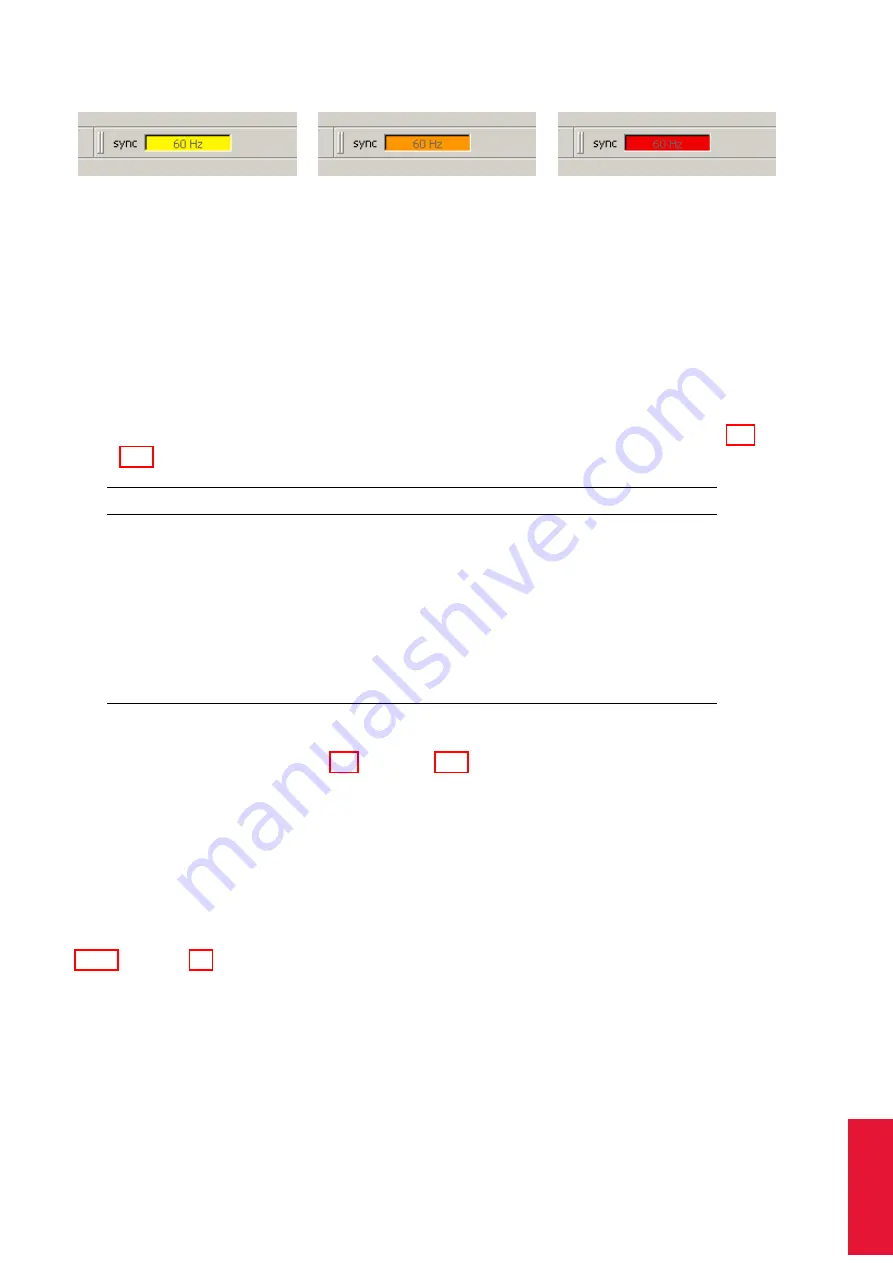
(a) yellow:
5 - 10 frames per
minute lost
(b) orange: 10 - 15 frames per
minute lost
(c) red: > 15 frames per minute
lost
Figure 8.6: Visualization of the synchronization frequency decrease
•
orange: 10 - 15 frames per minute lost
•
red: > 15 frames per minute lost
8.3.3 Docking Displays
By default the first three of the following docking displays are activated (see figure 8.5 on
page 132).
Docking Display
Description
Monitor 2DOF
Graphical display of all markers seen / tracked by the cam-
eras. Colour and shape represent the circularity and size of
the markers, respectively.
Data Display
Displays measurement results (6DOF and / or 3DOF)
Event Display
Displays
DTrack2
events (e.g. "no valid room calibration")
Fingertracking
Shows the measurement results of the hands
Flystick
Shows the measurement results (6DOF) of the Flystick and
the operation of buttons and joystick
Measurement Tool
Shows the measurement results of the Measurement Tool and
its reference body, if assigned
To change or activate the docking displays right-click anywhere on the toolbar or use the
menu
Display
(refer to chapter 8.7 on page 187. Drag & drop the display windows for
re-arrangement by left-clicking.
8.3.3.1 Monitor 2DOF display
The
Monitor 2DOF display
essentially is a 2-dimensional graphical display of all markers
/ flashes or other IR sources that can be seen inside the FoV of the cameras. It is par-
ticularly useful for the adjustment (especially orientation) of the cameras (refer to chapter
4.8.1 on page 48).
The
Monitor 2DOF display
shows a black window for each camera (equivalent to the field
of view) with a schematic display of positions, size and shape of all recognized markers.
Cameras per tab
In case several
ARTTRACK
cameras are being used in one system,
it may prove helpful to adjust the number of cameras shown in the
Monitor 2DOF display
135
Summary of Contents for Flystick3
Page 220: ...10 General Information 10 4 Declaration of conformity 220 ...
Page 221: ...10 4 Declaration of conformity 221 ...
Page 222: ...10 General Information 222 ...
Page 223: ...10 4 Declaration of conformity 223 ...
Page 224: ...10 General Information 224 ...
Page 233: ...10 4 Declaration of conformity 233 ...
Page 234: ...10 General Information 234 ...
Page 235: ...Appendix 10 4 Declaration of conformity 235 ...
Page 249: ...Appendix A A 7 System latency TRACKPACK Cascade discontinued 249 ...
Page 269: ...Appendix B B 3 Input of Special Control Data via Ethernet tfb 2 0 0 1 0 0 5 0 1 0 8 0 5 269 ...