CY8CKIT-049-4xxx PSoC® 4 Prototyping Kit Guide, Doc. #: 001-90711 Rev. *J
16
3.
Kit Operation
The PSoC 4 Prototyping Kit is simplistic in design and focuses on providing you with complete
access to develop applications using the PSoC 4 device family. The development kit supports a
number of onboard functions such as an LED, push button, through-hole connections, USB-Serial
connectivity to the PC, and a breakable board design to separate the two target boards.
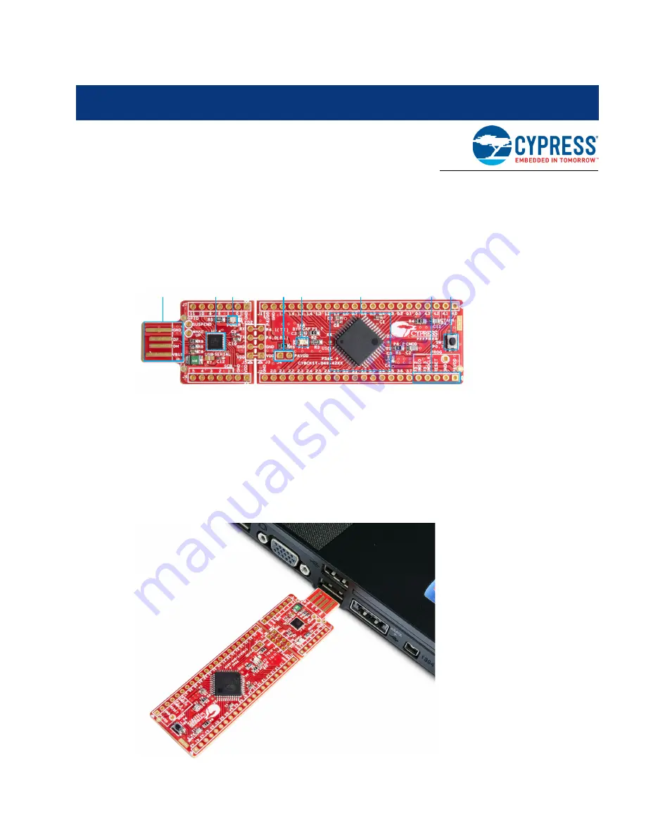
Figure 3-1. PSoC 4 Prototyping Kit
3.1
Connecting the PSoC 4 Prototyping Kit to a Computer
To use the PSoC 4 Prototyping Kit, you need to connect the kit to a target PC. The kit is designed to
be connected to the computer through USB. The USB connector will provide power to the target
boards and enable serial communication. CY8CKIT-049-4xxx implements a PCB-based USB
connector that makes connections to the USB port when plugged in. The amber LED turns on when
the board is plugged into the port to indicate power.
Figure 3-2. Connecting the PSoC 4 Prototyping Kit to a Computer
6
1. PCB USB Connector (J8)
2. USB-Serial Bridge Controller (U2)
3. Power LED (LED2)
4. Current Measurement Jumper (J4)
5. User LED (LED1)
6. PSoC 4 (U1)
7. Programming Header
8. Push button (SW1)
2
4
7
8
5
3
1
Summary of Contents for verical CYPRESS CY8CKIT-049-42 Series
Page 66: ...CY8CKIT 049 4xxx PSoC 4 Prototyping Kit Guide Doc 001 90711 Rev J 65 Appendix ...
Page 67: ...CY8CKIT 049 4xxx PSoC 4 Prototyping Kit Guide Doc 001 90711 Rev J 66 Appendix ...
Page 68: ...CY8CKIT 049 4xxx PSoC 4 Prototyping Kit Guide Doc 001 90711 Rev J 67 Appendix ...
Page 69: ...CY8CKIT 049 4xxx PSoC 4 Prototyping Kit Guide Doc 001 90711 Rev J 68 Appendix ...


