background image

VIP5602W Wireless IPTV Receiver Installation Guide

Wireless Connection

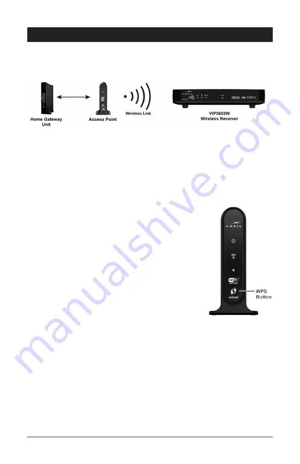
As shown in the diagram below, programs and services for the VIP5602W are transmitted 

over the air from a wireless Access Point. The Access Point, in turn, is connected to your 

home network gateway device. 

The Access Point can transmit separate programming streams to as many as five wireless 

IPTV Receivers. The Access Point uses Wi-Fi Protected Setup (WPS) protocols to identify, 

authorize, and manage traffic to and from its client devices. 

Register the TV Receiver with the Access Point

Before your TV Receiver can receive any programming, it must be registered as an 

authorized device with the Access Point. Run the WPS procedure as follows:

1.  Connect the cord from the DC Power Adapter to the POWER +12VDC connector 

on the rear of the VIP5602W, and plug the adapter into an 

AC wall socket. Then connect the VIP5602W to your TV 

set.

2.  The POWER button on the front of the wireless TV 

receiver lights green to indicate power is applied. 

3.  Ensure that the Access Point is connected to your home 

gateway device, and that power is applied to it.

4.  When the TV Receiver starts up, it will look for a signal 

from an Access Point. When it detects the signal, a 

prompt will appear on your TV screen asking if you wish to 

connect. 

5.  On the Access Point, press and hold the WPS button on 

the front panel for two seconds, then release to activate 

the WPS process.

6.  On the remote control unit, press the 

OK 

or

 Select 

button.

7.   An icon appears on the TV screen, indicating that the connection sequence  

is in process. When three horizontal dots appear, the connection  

has been successful.

8.  On the front panel of the VIP5602W, two or more bars on the signal  

strength indicator should light green. You have now established a  

secure wireless connection between the Access Point and your  

VIP5602W. 


NOTE: To install additional wireless TV receivers, repeat steps 1-7.

Wireless

Access Point

Summary of Contents for VIP5602W

Page 1: ...VIP5602W Wireless IPTV Receiver Installation Guide ...

Page 2: ...uctions Heed all warnings Follow all instructions Do not use this apparatus near water Clean only with a dry cloth Do not block any ventilation openings Install according to the manufacturer s instructions Do not install near any heat sources such as radiators heat registers stoves or other apparatus including amplifiers that produce heat Protect the power cord from being walked on or pinched part...

Page 3: ...port the receiver in its original factory carton or in an equally well padded container Whether installed or being transported do not expose the receiver to temperature extremes The temperature range for operation is from 0 to 40 C The non operating transport or storage temperature range is from 40 to 60 C WARNING TO PREVENT FIRE OR SHOCK HAZARD DO NOT EXPOSE THIS PRODUCT TO RAIN OR MOISTURE THE U...

Page 4: ...Introduction 1 Overview 2 Top View and Front Panel 2 Rear Panel 3 Wireless Connection 4 Connecting Your TV Receiver 5 Digital Audio Video Connections 7 Component Video and Digital Audio Connections 8 Composite Video and Stereo Audio Connections 9 Troubleshooting 10 ...

Page 5: ...onnection to consumer audio and video devices through multiple interfaces Bluetooth connectivity via remote control unit Refer to your service provider for more information This installation manual introduces the basic features outlines important safeguards and provides options for integrating your wireless receiver into your entertainment system Please take a few moments to read through this manu...

Page 6: ... light reflect the strength of the received signal the more bars the stronger the signal See the Troubleshooting section for details 3 LINK Wired Connection LED behavior No light No ethernet connection Off Blinking green Set top connecting to network Solid green Network connection enabled On Wireless Connection No light No wireless connection Blinking green Set top box pairing to Access Point or e...

Page 7: ...ESET BUTTON Press and release to trigger the System Recovery Process 4 OPTICAL TOSLink S PDIF digital audio output 5 BREAKOUT CABLE CONNECTION Alternative method for video audio connections Offers analog component composite and stereo audio outputs 6 HDMI OUT Connects to a High Definition TV or home theater receiver with an HDMI input for a DVI input use an HDMI to DVI adapter 7 USB 3 0 Allows con...

Page 8: ...n connect the VIP5602W to your TV set 2 The POWER button on the front of the wireless TV receiver lights green to indicate power is applied 3 Ensure that the Access Point is connected to your home gateway device and that power is applied to it 4 When the TV Receiver starts up it will look for a signal from an Access Point When it detects the signal a prompt will appear on your TV screen asking if ...

Page 9: ...anual supplied with the TV or on the TV itself Use the following guidelines to determine the best connections for your system Use one of the following Connector Description High Definition HDMI HDMI HDMI offers higher video quality than component video If your HDTV has an HDMI input use the HDMI connector HDMI provides both digital video and digital audio including Dolby Digital 5 1 Surround Sound...

Page 10: ...s Composite video provides a Standard Definition analog video signal using the video RCA connector yellow and the stereo audio RCA connectors white left red white Optical Audio If your equipment supports an optical S PDIF audio connection use the OPTICAL connection for the audio Common Cabling Examples The following cabling diagrams illustrate common sample audio video A V connections When connect...

Page 11: ...MI cable to the HDMI connector as shown The HDMI connection carries both digital video and digital audio signals If your HDTV has a DVI input you can use an HDMI to DVI converter to connect to the VIP5602W HDMI connector DVI video carries video signals only Use the optical audio or stereo audio connectors to provide audio output ...

Page 12: ... 5 1 Surround Sound If your HDTV has component inputs available connect the component outputs from a Breakout cable to the correct inputs on your HDTV as shown If your HDTV or A V Receiver has an optical audio input available use a Digital Optical Audio cable to connect from the VIP5602W to the correct input on your HDTV or TV Receiver as shown NOTE If you choose to configure stereo audio instead ...

Page 13: ... has composite video and analog stereo inputs connect the composite outputs using a Breakout cable to the correct inputs on your HDTV as shown Do not connect the unit through a VCR Video signals fed through VCRs may be affected by copyright protection systems and the picture will be distorted on the television ...

Page 14: ...ess receiver may be too large Stand in front of the wireless receiver and not too far to either side Press and release operation keys one at a time firmly and deliberately Try changing channels using the buttons on the wireless receiver front panel Check the batteries in the remote control Install new batteries if needed Video or Audio quality is poor or missing Verify the signal strength from the...

Page 15: ...he correct cables for the audio ports Verify that the audio cables are firmly connected between the wireless receiver and the audio playback device TV home theater receiver etc There is no audio from the center and or surround speakers of a home theater receiver connected to the wireless receiver Not all Dolby Digital programs feature full 5 1 surround sound In some cases the programs may only con...

Page 16: ...Radiation Exposure Statement The equipment complies with FCC radiation exposure limits set forth for an uncontrolled environment This equipment should be installed and operated with minimum distance of 20cm between the radiator and your body This transmitter must not be co located or operating in conjunction with any other antenna or transmitter Country Code selection feature to be disabled for pr...

Page 17: ...mply with the EIRP limit iii For devices with detachable antenna s the maximum antenna gain permitted for devices in the band 5725 5825 MHz shall comply with the EIRP limits specified for point to point and non point to point operation as appropriate and Operations in the 5 25 5 35GHz band are restricted to indoor usage only i Les dispositifs fonctionnant dans la bande 5 150 5 250 MHz sont réservé...

Page 18: ...ained in the Software programs or documentation 5 Export the Software or the Product components in violation of any United States export laws The Product is not designed or intended for use in on line control of aircraft air traffic aircraft navigation or aircraft communications or in design construction operation or maintenance of any nuclear facility ARRIS AND ITS THIRD PARTY LICENSORS DISCLAIM ...

Page 19: ...EXEMPLARY OR CONSEQUENTIAL DAMAGES INCLUDING BUT NOT LIMITED TO PROCUREMENT OF SUBSTITUTE GOODS OR SERVICES LOSS OF USE DATA OR PROFITS OR BUSINESS INTERRUPTION HOWEVER CAUSED AND ON ANY THEORY OF LIABILITY WHETHER IN CONTRACT STRICT LIABILITY OR TORT INCLUDING NEGLIGENCE OR OTHERWISE EVEN IF ADVISED OF THE POSSIBILITY OF SUCH DAMAGE IETF Sha1 License Text Copyright The Internet Society 2003 All R...

Page 20: ...S Logo are registered trademarks trademarks of ARRIS Enterprises Inc Dolby Digital manufactured under license from Dolby Laboratories Dolby and the double D symbol are registered trademarks of Dolby Laboratories This product incorporates copyright protection technology that is protected by U S patents and other intellectual property rights Use of this copyright protection technology must be author...

Page 21: ......

Page 22: ......

Page 23: ......

Page 24: ...599569 001 c 02 2017 Visit our website at www arris com ...

Reviews: