background image

28

Mattes

13

Mattes

Mattes help keeping stray light out of the lens front element.
Studio Matte Box mattes come in three variants:

Mattes SPH (Spherical): Spherical mattes for 4:3 sunshade. Not compatible

with 2:1 sunshade.

Mattes SPH / ANAM: Anamorphic mattes for 4:3 sunshade. Not compatible

with 2:1 sunshade.

Mattes ANAM: Anamorphic mattes for 2:1 sunshade. Not compatible with 4:3

sunshade.

Each matte set includes five different mattes and a protective cover. All mattes are

numbered. Matte #1 has the largest opening fitting wider angle lenses, matte #5 has

the narrowest opening fitting longer lenses. Please test mattes with the lens/camera

combination before the shoot.

13.1 Inserting a matte

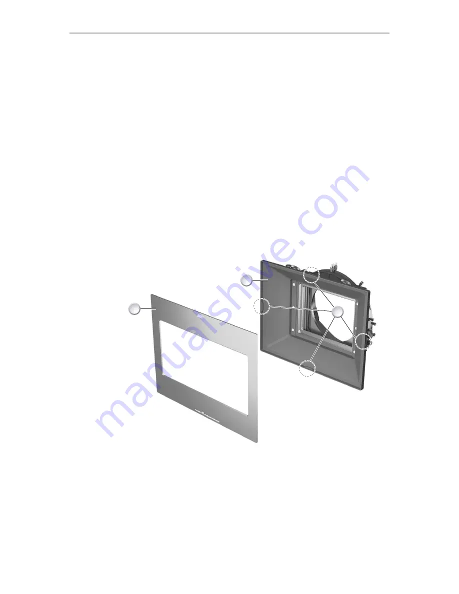
1

2

3

1. Fit the matte box to the camera rods.
2. Place the matte (1) of your choice at the front of the sunshade (2). The labelling of

the matte must face away from the matte box with the ARRI logo on top.

3. Engage the matte (1) by pressing on the four catches (3) around the sunshade

until they audibly lock.

4.

To remove: 

Ease the matte (1) off the four catches (3) and pull it away from the

sunshade (2).

Summary of Contents for SMB-1

Page 1: ...STUDIO MATTE BOX SMB 1 U S E R G U I D E 17 December 2014 STUDIO MATTE BOX SMB 1 U S E R G U I D E 17 December 2014 ...

Page 2: ...hter Cine Technik GmbH Co Betriebs KG Specifications are subject to change without notice Errors ommissions and modifications excepted Original version For further assistance Arnold Richter Cine Technik GmbH Co Betriebs KG Tuerkenstr 89 D 80799 Munich Germany E mail service arri com www arri com service Document revision history Version 1 0 ID 80 0003786 Release K08575 Date 17 December 2014 ...

Page 3: ... 16 9 2 Fitting a matte box on rods 17 10 Filter stages 18 10 1 Fitting a group of filter stages 18 10 2 Separating two filter stages 19 10 3 Rotating the filter stages 20 10 4 Geared filter frame 21 10 5 Tray catcher 22 11 Tilt and extension module 23 11 1 Tilt module 23 11 2 Extension module 24 12 Flags 25 12 1 Mounting Removing the top bottom flag 25 12 2 Mounting Removing a side flag 26 12 3 A...

Page 4: ...4 Contents 14 Accessory adapter 30 14 1 Mounting Removing an accessory adapter 30 14 2 Adapter operation 31 15 6 Tilting filter ring 32 15 1 Mounting Removing the 6 tilting filter ring 32 ...

Page 5: ...d signal words in these instructions indicate different risk levels CAUTION CAUTION indicates a potentially hazardous situation which if not avoided may result in minor or moderate injury NOTICE NOTICE explains practices not related to physical injury No safety alert symbol appears with this signal word ...

Page 6: ...nd all versions benefit from stackable filter stages allowing quick reconfiguration Uniquely both 4 3 and 2 1 ratio sunshades are available optimized respectively for spherical and anamorphic filming The Studio Matte Box SMB 1 covers the full ALEXA sensor area and allows the Master Prime 12 mm to be used with a 2 filter stage the Ultra Prime 10 mm with a 1 filter stage and the Ultra Wide Zoom UWZ ...

Page 7: ...Available versions 7 3 Available versions 1 2 1 SMB 1 Tilt K2 66262 0 2 SMB 1 Basic K2 0001516 ...

Page 8: ...8 Accessories 4 Accessories 1 2 3 5 4 1 Extension Module K2 0001519 2 Tilt and Extension Module K2 0001520 3 Top Bottom Flag K2 66273 0 4 Side Flags pair K2 66274 0 5 Side Flags ANAM pair K2 0001173 ...

Page 9: ...age incl 1 x Filter Frame non geared K2 0001462 2 2 Filter Stage incl 1 x Filter Frame non geared and 1 x Filter Frame geared K2 0001465 3 Sunshade ANAM K2 0001466 4 Mattes SPH K2 66267 0 5 Mattes SPH ANAM K2 0001161 6 Mattes ANAM K2 0000676 ...

Page 10: ...1 6 Tilting Filter Ring Ø150 mm K2 0001174 2 19 mm Studio Arm K2 66280 0 3 15 mm Studio Arm K2 0000646 4 Case for SMB 1 K2 0002669 5 Accessory Adapter K2 0001172 6 Flexible Shaft K2 34890 0 7 Top Bottom Flag Holders pair K2 0001517 ...

Page 11: ...bility The Studio Matte Box is compatible with the following ARRI accessories All R1 rings 165 mm check details online with ARRI Configuration Overviews All F1 filter frames check details online with ARRI Configuration Overviews ...

Page 12: ... necessary for matte box operation are fitted with a 3 mm Hex driver The dismantling of matte box components fastened with Torx head screws is not covered in this manual We recommend contacting an ARRI Service partner Tools needed 1 x 3 mm Hex driver ...

Page 13: ... Mounting Removing a sunshade Remove the sunshade in order to fit the anamorphic sunshade or for special applications when no sunshade is desired such as with macro shots 1 2 1 1 Fit the matte box to the camera rods or rest the matte box on its back 2 To remove Hold the sunshade 2 to the matte box and loosen all six screws 1 Note The screws 1 should stay captive in the sunshade 2 3 Remove sunshade...

Page 14: ...n The optional Anamorphic Upgrade Set comprises a 2 1 ratio sunshade a pair of side flags and a set of mattes matching the 2 1 ratio sunshade SMB 1 Anamorphic Upgrade Set K0 0001676 Sunshade ANAM K2 0001466 Side Flags ANAM pair K2 0001173 Mattes ANAM K2 0000676 NOTICE Each flag holder for the top and bottom flag can be repositioned by means of the two screws holding it to the matte box main frame ...

Page 15: ... away system 1 1 Fit the matte box to the camera rods 2 If necessary ease the lens rubber ring off the lens Alternatively extend the matte box with the extension module See Page 24 3 Pull the release plunger 1 while opening the matte box to the right of the camera until it locks automatically 4 Change or clean the lens 5 Pull the release plunger 1 and swing the matte box back onto the lens until i...

Page 16: ...upport is not compatible 9 1 Mounting Removing a matte box studio arm 1 2 1 Rest the matte box on its sunshade 2 Unlock the extension module 1 3 Extend the matte box by rotating the extension knob 2 clockwise 4 To remove If fully extended gently seperate the matte box and arm 5 To mount Insert the matte box arm by rotating the extension knob 2 anti clockwise and adjust the matte box extension if n...

Page 17: ...arm console by turning the wheel 5 anti clockwise 2 Slide the matte box onto the rods 4 with the extension closed 3 Lock both rods and the matte box by turning the wheel 5 clockwise 4 You can now raise or lower the matte box Loosen the 3 mm hex screw 2 on top of the arm Turn the height adjuster 3 with the same driver until you reach the required height To reset to standard height Align the white l...

Page 18: ...ompatible with the geared slot of the 2 filter stage NOTICE You can remove filter stages as a single module or in group 10 1 Fitting a group of filter stages 1 3 4 2 1 Remove the back plate 4 from the matte box if necessary Release the relevant release plunger 2 Pull the back plate 4 upwards 2 Slide the group of filter stages 1 from the top of the matte box Ensure that all sliding guides 3 are ful...

Page 19: ...Filter stages 19 10 2 Separating two filter stages 1 2 1 Pull the respective release plunger 1 2 Lift up and remove the redundant filter stage 3 Reattach the back plate 2 to the remaining filter stage ...

Page 20: ...ge features an anti friction coating and should not be greased or oiled 1 1 Fit the matte box to the camera rods 2 Install the filter stages to the matte box 3 Unlock the filter stage rotation by turning the rotation lock 1 anti clockwise slightly 4 Rotate the filter stage to the required angle 5 Lock the filter stage rotation by turning the rotation lock 1 clockwise ...

Page 21: ...ame 1 of a 2 filter stage module with the gear facing left 2 Turn the graduated filter frame wheel 2 located on the side of the 2 filter stage under the stackable stage release plungers This will lower or raise the geared filter frame 3 In order to follow camera tilt movement without touching the camera rig a flexible shaft 3 K2 34890 0 is available for step back adjustment ...

Page 22: ...tense filming such as vehicles and special effect shots NOTICE Do not force filter frames down when tray catchers are in use This could result in damage to the matte box 1 1 Slide the tray catcher 1 downwards 2 For filter movement e g graduated filter Retract the tray catcher 1 upward ...

Page 23: ...e box to the camera rods 2 Unlock the tilt module 1 3 Turn the tilt control 2 anti clockwise for tilt down and clockwise for tilt up 4 When the required effect is achieved lock the tilt module 1 5 The angle between two graduations 3 is 5 The limits of the tilt function are 20 down and 10 up 6 The tilt control knob is compatible with the flexible shaft K2 34890 0 for behind the viewfinder operation...

Page 24: ...Fit the matte box to the camera rods 2 Unlock the extension module 1 3 Move the matte box forward by turning the extension control 2 clockwise 4 Move the matte box backwards by turning the extension control 2 anti clockwise 5 When the required extension is achieved lock the extension module 1 ...

Page 25: ...box main frame in order to suit either the 4 3 or 2 1 sunshade 1 2 3 4 3 4 1 Open the two flag holder nuts 4 slightly until a gap of around 4 mm is visible 2 Engage the top flag cut outs 3 in the flag holder 3 To mount Lock the top flag in place by fastening the flag holder nut 4 4 To remove Open the two flag holder nuts 4 slightly and pull the top flag out 5 Adjuster 2 for quick and fine adjust s...

Page 26: ...or quick and fine adjust see Adjusting the flag angle 12 3 Adjusting the flag angle CAUTION Moving parts and hinges Risk of injury Sharp edges may entail pinches Keep fingers away from potential pinching spots NOTICE The flag adjuster mechanism features self lubricating components and should not be greased or oiled All flags are fitted with adjusters for quick and fine adjustment Use quick adjustm...

Page 27: ...ving part of the flag with a hand 3 Depress the quick adjust button 1 and keep depressed 4 Adjust the flag angle to the desired position 5 Release the quick adjust button 1 12 3 2 Fine adjust 1 1 Turn the fine adjust knob 1 until the desired angle is reached Anti clockwise for tilt down Clockwise for tilt up ...

Page 28: ... protective cover All mattes are numbered Matte 1 has the largest opening fitting wider angle lenses matte 5 has the narrowest opening fitting longer lenses Please test mattes with the lens camera combination before the shoot 13 1 Inserting a matte 1 2 3 1 Fit the matte box to the camera rods 2 Place the matte 1 of your choice at the front of the sunshade 2 The labelling of the matte must face awa...

Page 29: ...shots or if leaving the camera unattendend each matte set includes a protective cover 1 3 2 1 Fit the matte box to the camera rods 2 Place and engage the protective cover 2 on the sunshade 3 See Page 28 3 To remove Engage a finger into the round aperture 1 and firmly pull the matte away from the sunshade ...

Page 30: ...DM 1 14 1 Mounting Removing an accessory adapter 4 1 3 2 1 Fit the matte box to the camera rods or rest the matte box on its sunshade and arm 2 Place the accessory adapter 1 on top of the matte box 3 Engage the locating pins 2 into the slots 3 located on top of the matte box 4 To mount Tighten the two screws 4 with an 3 mm Hex driver 5 To remove Loosen the two screws 4 with an 3 mm Hex driver and ...

Page 31: ...desired position 3 Lock the 3 8 mount lock 2 Sprung ball bearings are located on each side of the accessory mount preventing the accessory adapter to fall off The accessory adapter can be removed e g to be placed on another matte box by pulling the accessory adapter firmly through the sprung ball bearings ...

Page 32: ... Ø150mm R8 screw in rings 15 1 Mounting Removing the 6 tilting filter ring 1 2 3 1 Engage the tilting filter ring 1 by pressing it into the filter stage until it audibly locks 2 To mount Lock the tilting filter ring 1 in position 3 To remove Unlock the tilting filter ring 1 and pull it off the filter stage 4 To seperate Rotate both parts 1 2 against each other in order to loosen the two halves 5 F...

Reviews: