Array electronic 3645A User Manual Download Page 10


10

3645A Programmable Power Supply

ARRAY ELECTRONIC  CO.,LTD  2002.3

 3645A-TYPE  USER’S MANUAL

2.3.4 Store data function

To users, this is a good function for ease using. If you wan to use a constant voltage and

current as 24V and 2A, or 12V and 2.3A etc every day, you just need to set up the data for the

first time, and then store the data in the power supply, and then recall it when you need the data

again. It can store 10 sets data at most.

The stored contents include 1) Voltage value; 2) Current value; 3) Maximum voltage; 4)

Locked/unlocked key board; 5) Maximum power ; 6)Baud rate; 7) Communication address.

The store operation always be done after setting up V-set, I-set etc, the operation is as following:

For example

, set up the voltage=15V, current=2A, Maximum output voltage=18V, key board

locked, Maximum output power=25W, Baud rate=9600, communication address=05, after done

the setup , users can store all the above setup as a set of data, such as the 01 or 02 etc set date.
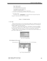
Procedure

    The operation Methods                                                       LCD display

     Step 1       Press “Store” button                                                              ****V   ****W

                                                                                                                ****A   **

Step 2       Enter the password ( Or jump to step 4 if the keyboard         ENTER PASSWORD

                 is unlocked)

Step 3       Press “Enter” button ( it will return to step 2 if your            ENTER PASSWORD

                 password is wrong for reentering)                                         1234

Step 4      Enter the set value for store number(from 1 to 10) by         STORE  1

                using the number key or rotate the rotary button to

                change the set value number for store

Step 5      Press “Store” button to confirm the set value, if the               STORE  *

                number is out of the range from 1 to 10, it will retune to

                Step 2 for reenter

            It will exit the store operation at any procedure by press ESC button

Summary of Contents for 3645A

Page 1: ...3 6 1 Set up the maximum voltage output value 0 36V 12 2 3 6 2 Set up the key sound 13 2 3 6 3 Set up the communication 13 2 3 6 4 Set up communication address 0 254 13 2 3 6 5 Set up locking key boar...

Page 2: ...safety ground at the power outlet For instruments designed to be hard wired to the AC power lines supply mains connect the protective earth terminal to a protective conductor before any other connecti...

Page 3: ...ght 5 5Kg Accessories Software users manual AC power cable handlebars Communication cable for RS232 Communication cable for RS485 Mounting rack 3645A Type programmable DC power supply is designed and...

Page 4: ...5 Protection for over or lower current 6 Adjustable voltage and constant voltage output 7 Adjustable current and constant current output 8 Can be set for maximum current protection 9 Can be set by num...

Page 5: ...tom Conner The output power value Flashing power value means the over power The Right upper Conner The output current value The Right bottom Conner The state value In common state the keyboard will ex...

Page 6: ...eration The right moving key ESC Can be used to exit any working state OK Confirmation key Rotary SW The rotation key Fig5 Rotary and function keys 1 4 2 2 Back view The fuse can be changed easily by...

Page 7: ...f date which had been set up 5 Recall the stored data 2 2 2 Sub functions 1 Set up the output voltage limit 2 Turn ON OFF the sound of key 3 Set up the communication 4 Lock ON OFF the key board 5 Set...

Page 8: ...of the value which is indicated on the LCD you can move the cursor to the first number second number etc by using and buttons and then rotate to change each number and let it stay at 24 3 V then confi...

Page 9: ...hould be off when it is powered users can change the output status by using ON OFF button The button is a turn over button when the original output is ON press the button then the output will be chang...

Page 10: ...mple set up the voltage 15V current 2A Maximum output voltage 18V key board locked Maximum output power 25W Baud rate 9600 communication address 05 after done the setup users can store all the above s...

Page 11: ...power 6 Baud rate 7 Communication address The recall operation is as following Procedure The operation Methods LCD display Step 1 Press Recall button 0 000V 0 00A 0 00W OFF Step 2 Enter the password...

Page 12: ...display the menu functions one by one user MAX OUT VOLTAGE can use the UP and DOWN button to change the KEY SOUND SET selecting each function Press Enter button to execute COMMUNICATION SET the select...

Page 13: ...be your password and confirm the password by pressing Enter button 2 3 6 3 Set up the communication This function is for monitoring the output data of the power supply by using a computer When you se...

Page 14: ...ly is powered on for every time When you select the SAVE OPTION function the LCD will display as SAVE VOLTAGE DON T SAVE VOLT 2 3 6 8 EXIT function When the EXIT function is selected you will exit the...

Page 15: ...lation Initial Interface 3 1 2 Then it will enter the interface as in Fig 3 2 Press NEXT to continue Fig 3 2 The Installation Interface 2 3 1 3 In Fig 1 3 there is some explanation to some products in...

Page 16: ...tinue Fig 3 5 The Installation Interface 5 3 6 In Fig 3 6 enter the file folder s name and the default name is POWERMS Generally it is not needed to enter and it is just need to click NEXT Fig 3 6 The...

Page 17: ...e initial interface as shown in Fig 3 9 Fig 3 9 The System Start Diagram 3 2 3 Wait for the end of the system initialization and then it will enter the main interface as shown in Fig 3 10 Fig 3 10 The...

Page 18: ...e only the COM port set and the POWER selection can be carried out and other function cannot be used So users must login and operate and it guarantees the security of the system Select the icon and th...

Page 19: ...rame as shown in Fig 4 4 will be displayed Fig 4 4 COM Port and address set In Fig 4 4 select the page key COM and select the COM port from the pull down table If the COM port does not exit the system...

Page 20: ...address of the power cannot be set and the prompting diagram as shown in Fig 4 7 will be displayed This time the communication cable must be checked Fig 4 7 Communication Failure Explanation For the f...

Page 21: ...mouse to the icon and then rotate the button 2 Using the keyboard Select the V button enter the data and then select the OK button There are two methods to set the voltage range one is by using the ro...

Page 22: ...l be displayed Fig 4 16 Users Manage 1 Append User Select the page key APPEND and the user type generally is General Enter the user s name cannot be blank and the password twice must be the same and t...

Page 23: ...up Fig 4 19 Deleting User Prompting Explanation Manager and Lowest are retained by the system and cannot be deleted 4 Event Select the page key EVENT and the dialogue as shown in Fig 4 20 will be dis...

Page 24: ...button and all the records agreed with the conditions will be listed 3 Set the Report Select REPORT and it will be OK 4 Print the Report Select PRINT and it will be OK 5 Query Totally Select TOTAL an...

Page 25: ...Running Diagram 3 Keyboard Explanation Number Keys 0 9 the point key C the clearing key the backspace key V the voltage setting key Unit V 0 36 000 A the current setting key Unit A 0 3 000 mV the volt...

Page 26: ...ompany and so on Select the icon and the system will automatically be in the lowest limit of authority User must login again for the operation When leaving the user must carry out the canceling operat...

Reviews: