background image

507607-03

Issue 1827

Page 5 of 23

Line Set Isolation

The following illustrations demonstrate procedures that 

ensure proper refrigerant line set isolation. Figure 7 shows 

how to install line sets on horizontal runs. Figure 8 shows 

how to make a transition from horizontal to vertical. Figure 

9 shows how to install line sets on vertical runs.

Table 2. Refrigerant Line Set Diameters (in.)

Model

16 SEER

Liquid Line

Suction Line

24

3/8

3/4

36

3/8

7/8

48

3/8

7/8

60

3/8

1-1/8

For lines longer than 50 ft., refer to long line set guidelines.

Brazing Connection Procedure

1.  Cut ends of refrigerant lines square (free from nicks or 

dents). Debur the ends. The pipe must remain round; 

do not pinch end of line.

2.  Before making line set connections, use dry nitrogen 

to purge the refrigerant piping. This will help to prevent 

oxidation and the introduction of moisture into the 

system.

3.  Use silver alloy brazing rods (5% or 6% silver alloy 

for copper-to-copper brazing or 45% silver alloy for 

copper-to-brass or copper-to-steel brazing) which are 

rated for use with R410A refrigerant.

4.  Remove the Schrader core assemblies before brazing 

to protect them from damage due to extreme heat. 

Replace the cores when brazing is complete.

5.  Remove light maroon washers from service valves 

and shield light maroon stickers to protect them during 

brazing. Wrap a wet cloth around the valve body and 

copper tube stub to protect it from heat damage.

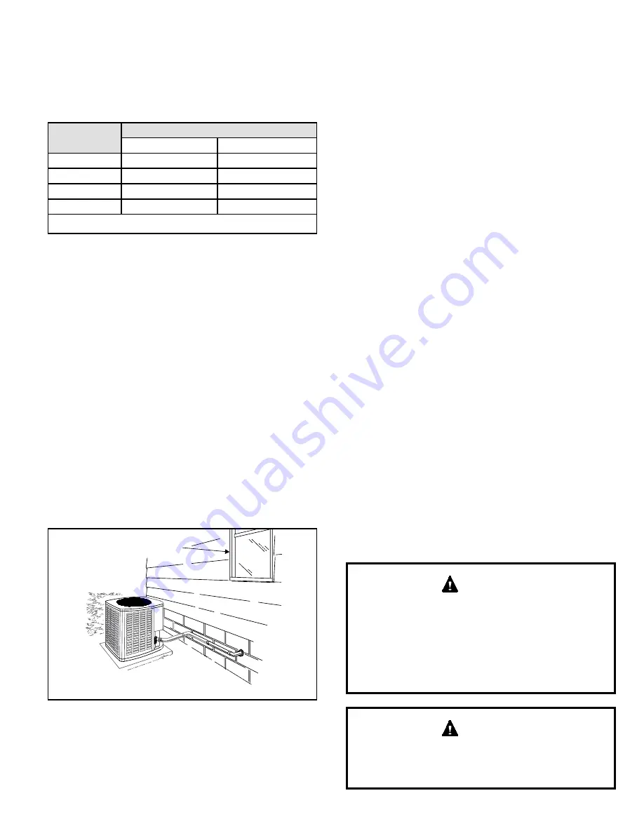
Install unit away

from windows

Two 90° elbows installed in lineset

will reduce lineset vibration

Figure 6. Outside Unit Placement and Installation

6.  Braze the line set to the service valve. Quench the 

joints with water or a wet cloth to prevent heat damage 

to the valve core and opening port. The tube end must 

stay  bottomed  in  the  fitting  during  final  assembly  to 

ensure proper seating, sealing, and rigidity.

7.  Install the thermal expansion valve which is sold 

separately and which is approved for use with R410A 

refrigerant in the liquid line at the indoor coil (see 

Refrigerant Metering Device section).

Refrigerant Piping

If the 4SCU16 LS unit is being installed with a new indoor 

coil and line set, the refrigerant connections should be 

made as outlined in this section. If an existing line set and/

or indoor coil will be used to complete the system, refer 

to this section as well as the section that follows entitled- 

Flushing Existing Line Set and Indoor Coil.

If this unit is being matched with an approved line set 

or indoor coil which was previously charged with R-22 

refrigerant, the line set and coil must be flushed prior to 

installation. If the unit is being used with an existing indoor 

coil which was equipped with a liquid line which served as 

a metering device (RFCI), the liquid line must be replaced 

prior to the installation of the 4SCU16 LS unit.

Field refrigerant piping consists of liquid and suction lines 

from the outdoor unit (sweat connections) to the indoor coil 

(flare or sweat connections).

Select line set diameters from Table 2 to ensure that oil 

returns to the compressor. Size vertical suction riser 

to maintain minimum velocity at minimum capacity. 

Recommended line length is 50’ or less. Table 2 shows 

the diameters for line sets up to 100’ although vertical lift 

applications and trapping requirements need to be reviewed 

for line sets over 50’; refer to long line set guidelines.

Installing Refrigerant Line

During the installation of an air conditioning system, it is 

important to properly isolate the refrigerant line to prevent 

unnecessary vibration. Line set contact with the structure 

(wall, ceiling, or floor) may cause objectionable noise when 

vibration is translated into sound. As a result, more energy 

or vibration can be expected. Close attention to line set 

isolation must be observed.

When  flushing  existing  line  set  and/or  indoor  coil,  be 

sure to empty all existing traps. Residual mineral oil can 

act as an insulator, preventing proper heat transfer. It 

can also clog the thermal expansion valve, reducing 

system performance and capacity. Failure to properly 

flush system as explained in these instructions will void 

warranty. 

 CAUTION

If ANY refrigerant tubing is required to be buried by state 

or local codes, provide a 6 inch vertical rise at service 

valve. 

 CAUTION

Summary of Contents for 4SCU 16 LS Series

Page 1: ...personal injury death or property damage Use appropriate safety gear including safety glasses and gloves when installing this equipment WARNING Risk of electrical shock Disconnect all remote power sup...

Page 2: ...lbs Service Port Caps 8 ft lbs Sheet Metal Screws 16 in lbs 8 Machine Screws 16 in lbs 10 Machine Screws 28 in lbs Compressor Bolts 90 in lbs Inspection of Shipment Upon receipt of equipment carefull...

Page 3: ...it properly can result in personal injury or death WARNING Line voltage is present at all components when unit is not in operation on units with single pole contactors Disconnect all remote electric p...

Page 4: ...to terminal C Single wire to terminal C Unused wires Unused wires Comfort Sync Thermostat with a Non Communicating Outdoor Unit ENABLED FURNACE Comfort Sync THERMOSTAT NON COMMUNICATING OUTDOOR AIR CO...

Page 5: ...evice section Refrigerant Piping If the 4SCU16 LS unit is being installed with a new indoor coil and line set the refrigerant connections should be made as outlined in this section If an existing line...

Page 6: ...ne only 8 8 Tape or Wire Tie Strap the vapor line to the joist or rafter at 8 intervals then strap the liquid line to the vapor line Floor Joist or Roof Rafter Metal Sleeve Floor Joist or Roof Rafter...

Page 7: ...507607 03 Issue 1827 Page 7 of 23 Figure 9 Refrigerant Line Sets Installing Vertical Runs Figure 10 Flushing Connections...

Page 8: ...voltage and line voltage connections to the new outdoor unit Do not turn on power to the unit or open the outdoor unit service valves at this time 4 Remove the existing R 22 refrigerant flow control o...

Page 9: ...ling the higher system operating pressures The gauges should be rated for use with pressures 1 800 on the high side and a low side of 30 vacuum to 250 psi with dampened speed to 500 psi Gauge hoses mu...

Page 10: ...w R410A into the line set and indoor unit Weigh in a trace amount of R410A A trace amount is a maximum of 2 oz of refrigerant or 3 lbs pressure Close the valve on the R410A cylinder and the valve on t...

Page 11: ...et disconnect the manifold hose from the vacuum pump Open the service valves to break the vacuum in the line set and indoor unit Start Up If unit is equipped with a crankcase heater it should be energ...

Page 12: ...perature 5 When the heating demand has been satisfied switch the thermostat to cooling mode with a set point of 68 F When pressures have stabilized use a digital thermometer to record the liquid and s...

Page 13: ...5 50 45 40 55 50 45 40 55 50 45 40 ON OFF 30 PSC LO PS HI PS Y1 OUT Y2 OUT OUT O R I I C DS O Y1 Y2 L W COIL AMB DIS OPEN OFF OPEN 90 F 2ND STAGE LOCK IN 55 F 50 F 45 F 40 F DEFROST TERMINATION 100 F...

Page 14: ...unit control circuit is isolated from power and the field supplied relays bypass the outdoor thermostats An amber indicating light simultaneously comes on to remind the homeowner that the unit is ope...

Page 15: ...ers Verify configuration of system Communicating systems only Reconfigure the system Replace control if heating or cooling is not available Only applicable in the communicating mode not in startup Exi...

Page 16: ...he recommended upper limit of 279 F Discharge line high temperature error count reached 5 strikes Confirm that the system is properly charged with refrigerant Check system operating pressures and comp...

Page 17: ...C 2AC 1 Stage AC 1HP 1 Stage AC 2HP Power Up 7 Segment Display String 2 H P ___ ___ ___ ___ ___ ___ Unit Type Stages No Capacity No Fan Profile Power Up Reset following display of self discovered conf...

Page 18: ...1 E pause 250 pause E pause 231 Next codes up to 10 are shown using same method If there are no error codes stored E pause 000 Fault Memory Clear After the fault memory is cleared the following string...

Page 19: ...ode string d pause F Outdoor fan RPM pause A ambient temp displayed pause repeat mode IMPORTANT On 2 stage unit R to DS link must be cut and correct RPM outdoor fan profile selected for outdoor fan to...

Page 20: ...will automatically exit Field Test Mode If 10 second period expires or push button is held for less than 3 seconds control will automatically exit Field Test Mode and go into Idle Mode without storin...

Page 21: ...nd all access panels must be in place any time the unit is in operation Some systems are equipped with an electronic air cleaner designed to remove the majority of airborne particles from the air pass...

Page 22: ..._____________ Rated Load Ampacity _______________ Compressor Amperage _________________ OutdoorFan _____________________ Maximum Fuse or Circuit Breaker ____________________________ Electrical Connect...

Page 23: ...507607 03 Issue 1827 Page 23 of 23 Figure 15 4SCU16LS124 36 48 60 Wiring Diagram...

Reviews: