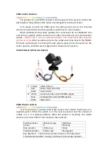


PWM control function:
The gimbal can use PWM channels (control signal of the servo) to control the
pitch angle of the gimbal and the camera recording start and stop function;
First, please connect the PWM signal line with ground wire to the channels
which are controlled by the three-positions switch of your radio receiver.
When switched to the center position, the camera will be on STAND-BY. One
end of the 3 position switch will be record video, the other one end will be take a
picture .
NOTE
:
This is not an automatic shooter. The camera will take only one
picture at a time.
After you take a picture, the camera will come back to the STAND-
BY status automatically. For taking the next picture, please move the switch to the
center position and then switch it again to the “take picture” position.
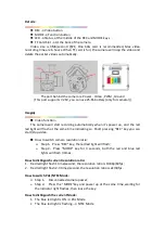
Gimbal Details: (Wires description)
A Yellow
Video Output
Red
Power input (9-12.6V)
Black
Ground wire
B
White
Camera shooter control (PWM signal)
Blue
Gimbal pitch control (PWM signal)
Black
Signal wire
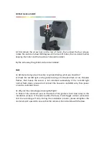
PWM Shooter Control:
(1) The white line is used to control the camera. The remote control uses a 3-
segment switch. When the switch is in the neutral position and the amount of
rudder is 0, it is a waiting interface. When the camera is recording, the rudder
volume is less than -50% for the camera to take a picture.
Switch position
Channel range
Definition
Center
0
Stand-by
Max position
+50% or up
Video
Smallest position
-50% or less
Photograph
Pay attention: There's burst pictures function. The next photo
should be started after moving switch back to the center position.


