Arjohuntleigh Maxi Sky 600 Technical Manual Download Page 11

11

Service Procedures

00

1.

14

15

5.3

3

 r

ev

. 8

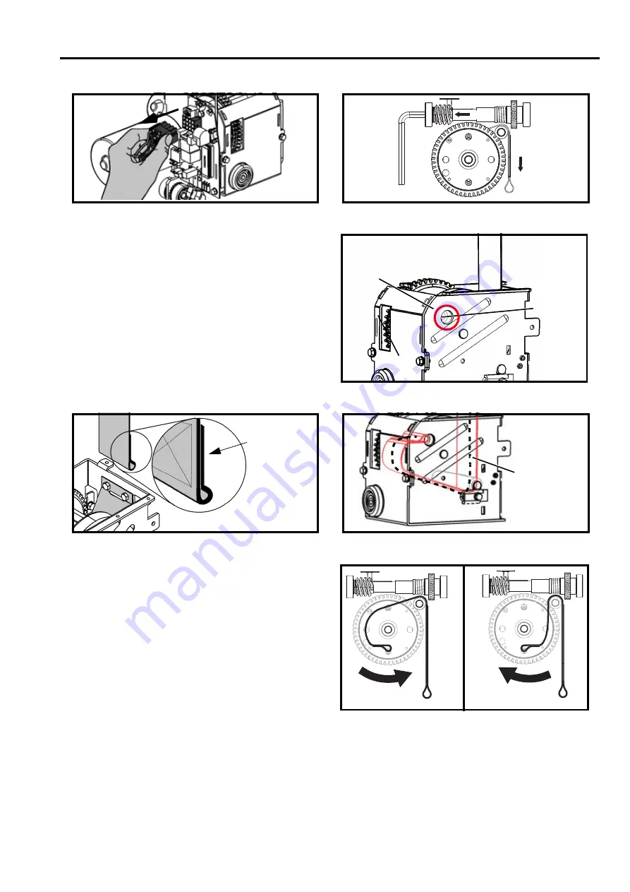
b. Unwind the strap completely.

4)

Rotate the drum to align the strap bolt with the large 
hole on the frame (see Fig. 13).

5)

Completely unscrew the strap bolt with a 6 mm Allen 
key and remove the old strap.

FOR LIFTS EQUIPPED WITH LIMIT PLATE
(200.14070)

6)

Guide the new strap between the limit plate and the 
plastic roller making sure to place the folded part 
facing the limit plate (see Fig. 14 and Fig. 15).

7)

Align the loop of the strap with the hole of the 
retaining bolt.

8)

Reinsert the bolt and tighten.

9)

Rewind the strap. Make sure it is in the correct 
winding direction (see Fig. 16). 

10) Grease the drum teeth with food-grade grease (refer 

to “Parts List” manual for part number).

Fig. 11

Fig. 12

Fig. 14

Fig. 15

(a)

(b)

Fig. 13

Large

hole

Strap

bolt

Folded part
facing the
limit plate

Strap path

Fig. 16

Correct

Wrong

Summary of Contents for Maxi Sky 600

Page 1: ...Maxi Sky 600 Technical Manual 001 14155 33 rev 8 December 2017 ...

Page 2: ...joHuntleigh group of companies ArjoHuntleigh 2017 As our policy is one of continuous improvement we reserve the right to modify designs without prior notice The content of this publication may not be copied either whole or in part without the consent of ArjoHuntleigh ...

Page 3: ...edure 10 Replacement of Vertical Motor 18 Service Procedure 11 Replacement of Horizontal Motor 19 Service Procedure 12 Fuse replacement 19 Connection Diagram Main Connector 20 Service Procedure 13a 13e ECS Track System 20 Care and Maintenance 27 Preventive Maintenance Schedule 27 User Inspections 27 Inspections by an Authorized Service Technician 28 Cleaning 29 Strap Inspection 30 Emergency Brake ...

Page 4: ...t modifications without the revision of this manual or that the contents of this manual changes without prior notice to users ArjoHuntleigh designs and manufactures quality engineered patient lifting equipment for the care of the elderly and disabled in home care nursing homes and other health care facilities Please take the time to read the entire manual including the section on Safety Instructio...

Page 5: ...ck nameplate for voltage and frequency requirements These requirements differ by country Do not attempt to use the lift in an area that has a different voltage and cycle requirement Fire and Explosion Prevention Do not dispose of batteries in fire Do not short the battery terminals For recycling and disposal of the batteries the rules according to the WEEE directive Waste of Electronic and Electri...

Page 6: ... Emergency lowering mechanism 3 Allen key 4 Track 5 Charging station 6 Strap 7 Spreader bar 8 Handset 9 Red emergency pull cord 10 Safety latch 11 UP button 12 DOWN button 13 Green power light 14 Emergency switch plastic insert 15 Yellow charging light 16 Red maintenance overload light 17 Cord connected charger 18 Wall adapted charger 6 ...

Page 7: ...tteries are low The red light illuminates to confirm that the lift is in the programming mode The red light also illuminates in the normal mode when the lift goes into overheat protection caused by overuse The red light flashes when servicing is required contact customer service Hand Control The Maxi Sky 600 hand control can be infrared or wired Universal Charger The Maxi Sky 600 comes equipped wi...

Page 8: ...ed cord 2 Remove the spreader bar 3 Place the Maxi Sky 600 on a solid table with the trolley facing downwards Use pieces of wood under each side of the trolley to stabilize it and prevent it from moving Make sure not to damage the contact blades 4 Unsnap and completely remove the panel by pushing on both ends see Fig 2 this will expose the batteries 5 Disconnect the batteries Remove them by unscre...

Page 9: ...ing the red cord 2 Unsnap and completely remove the bottom panel by pushing on both ends see Fig 2 3 Disconnect the batteries see Fig 9 4 Unscrew the 4 screws using a T 20 Torx screwdriver 5 Pull out the batteries 6 Connect the new batteries Make sure to respect the polarity by matching wire colors with the marks on the batteries red to red black to black 7 Screw the support plates back in 8 Reass...

Page 10: ...o J3 of the new Brake Board Circuit 5 Insert the main cable connector to the new Brake Board 6 Insert the new Brake Board into the Main Circuit see Fig 10_b 7 Reassemble the unit by performing service procedure 9 Service Procedure 5 Replacing the Strap 1 Remove the plastic shell by performing service procedure 1 steps 1 to 9 2 Disconnect the main connector from circuit board This will open the mot...

Page 11: ... the limit plate and the plastic roller making sure to place the folded part facing the limit plate see Fig 14 and Fig 15 7 Align the loop of the strap with the hole of the retaining bolt 8 Reinsert the bolt and tighten 9 Rewind the strap Make sure it is in the correct winding direction see Fig 16 10 Grease the drum teeth with food grade grease refer to Parts List manual for part number Fig 11 Fig...

Page 12: ...the drum 10 Join the kit s two halves together again using the T 20 Torx screws 11 Lower the high limit switch kit into place and reinstall the socket head screws see Fig 20 12 Align the loop of the strap with the hole of the retaining bolt 13 Reinsert the bolt and tighten 14 Rewind the strap Make sure it is in the proper winding direction see Fig 16 15 Grease the drum teeth with food grade grease...

Page 13: ... lift s SWL to the spreader bar refer to the specifications sheet of the ceiling lift user s manual or the label on the lift to determine the SWL rating Press the UP button to verify if the unit can lift the load up until the strap is fully wound Lower the weight and remove it from the spreader bar Service Procedure 7 Replacing the High Limit Switch 1 Remove the plastic shell from the chassis by p...

Page 14: ...ssemble the unit FOR LIFTS EQUIPPED WITH THE HIGH LIMIT SWITCH KIT 700 14075 4 Loosen the high limit switch kit assembly by removing the 2 socket head cap screws with the 4 mm Allen key see Fig 26 5 Slide out the high limit kit assembly kit 6 Unscrew the 2 T 20 Torx screws see Fig 26 7 Route the new strap between the two halves of the high switch limit kit 8 Join the kit s two halves together agai...

Page 15: ...the circuit board 9 Refer to the service procedure 9 to reassemble the plastic housing 10 Before putting the lift back in service perform a weight load test Attach a weight equivalent to the ceiling lift s SWL 272 kg 600 lb to the spreader bar Press the UP button to verify if the unit can lift the load up until the strap is fully wound Lower the weight and remove it from the spreader bar Service P...

Page 16: ...oard making sure that the ferrite is not interfering inside the battery cavity and that the cable is secured passing through the cord grip built inside the main shell see Fig 34 Note If unit is not equipped with a ferrite add a ferrite to the cable of the current handset and route the cable as shown on Fig 35 Fig 34 Fig 35 Fig 33 A A A A B B B B Connector Cord grip Ferrite Route the cable around t...

Page 17: ...nstall the alternate buttons by snapping it into the opening see Fig 37 10 Replace the bottom cover Pass the strap through the center opening Pass the hand control wire through the small slot and align the up and down buttons 11 Snap the clips on at each end and near the strap opening Note This step only applies to lift with serial Number below XX XXXX 17750 12 Turn on the lift Note For the first ...

Page 18: ...oves It is very important to position the motor housing in the same orientation as it was prior to disassembling i e that the mark is positioned upward see Fig 41 and making sure that the contact point of the wires inside the motor are placed above the shaft see Fig 42 Plug the motor wires into the main connector making sure to place the red wire into position 11 and the blue wire into position 12...

Page 19: ...ement motor in place 8 Screw the new motor back onto its support Replace the gear using a small plastic hammer Carefully fit the D shaped hole with the D shaped shaft 9 Align the gear with the trolley s gear and screw the motor support back onto the trolley 10 Reconnect the wires to the main connector Make sure to respect polarity as failure to do so will reverse motor displacement Refer to main c...

Page 20: ...ition 2 No connection Position 3 Blue Horizontal motor Position 4 Blue High limit switch Position 5 No connection Position 6 Red Horizontal motor Position 7 No connection Position 8 Blue High limit switch Position 9 Black White Chassis ground Position 10 Orange On Off switch Position 11 Red Vertical motor Position 12 Blue Vertical motor Service Procedures 13a 13e for ECS Track System The Maxi Sky ...

Page 21: ...ing on the red cord However to turn the cassette back on again a plastic insert switch must be pressed upwards instead see Fig 48 Fig 48 Service Procedure 13b Changing the Trolley s ECS Contact Box 1 Using pliers to hold the contact box loosen the two connectors attached to it on either side 2 Once the connectors are removed slide the contact box out from the opening in the trolley 3 Replace the c...

Page 22: ...ess cable from under the loosened cable guard Remove the topshell housing to get access to the unit s frame Unplug the ECS circuit board connector You can now dispose of the cable Connect the new ECS wire harness cable to the ECS circuit board After replacing the upper plastic housing thread the cable back into the cable guard on the trolley and reinstall the screw Reinstall the ECS contact box an...

Page 23: ...uit board s connector Install the new ECS board on coupling it to the main circuit board s connector Ensure that the spacer is placed between the main and ECS circuit boards see Fig 4 Reinstall the screw that secures the ECS board to the frame CAUTION When reinserting the ECS circuit board be careful to align the connector pins perfectly to their socket to avoid breaking them Remove using an 8 mm ...

Page 24: ... the circuit board 2 Unplug main circuit board connector and the wires to the on odd switch 3 Unscrew the bolts that secure the main circuit board to the frame using an 8 mm 5 16 socket 4 Slide out the plastic insert Thread the red emergency cord into the new plastic insert 5 Make sure that the plastic insert switch is placed between the circuit and the frame 6 Reinstall the circuit board and circ...

Page 25: ... 2 Not used 3 Red Lateral motor 4 Blue High limit switch 5 Not used 6 Blue Lateral motor 7 Not used 8 Blue High limit switch 9 Black white Battery 10 Orange From switch 11 Red Vertical motor 12 Blue Vertical motor On Off Toggle Switch Wiring Connections 1 Red white Main connector position 1 2 Orange Main connector position 10 3 Red white Cable 4 Orange Cable 1 2 3 4 ...

Page 26: ...26 ...

Page 27: ...manufacturer A load test for the ceiling lift is recommended Preventive maintenance specified in this manual can prevent accidents and reduce repair costs WARNING Safety related maintenance and authorized service must be carried out by qualified personnel fully trained in servicing procedures by ArjoHuntleigh and equipped with proper tools Failure to meet these requirements could result in persona...

Page 28: ... bar on the strap of the lift for damage or cracks Make sure all attachments are properly secured e g split ring X FREQUENCY Inspection for lift Initially Before every use Every two months or 500 cycles Every four months or 1000 cycles Every year or 2500 cycles Every two years or 5000 cycles Replace strap X Inspect frame parts interlock and hardware for malfunction and make sure there are no parts...

Page 29: ...tions for rails Initially Before every use Every two months or 500 cycles Every four months or 1000 cycles Every year or 2500 cycles Every two years or 5000 cycles Torque end stoppers to 20 N m 15 lbf ft X X Make sure that the bracket locking device is not visible X X Make sure rail joints are closed and that the spring pins are centered X X Make sure the rail is straight when it is not loaded X X...

Page 30: ...t procedure for both locks Units from serial number 84854 and above 1 Rotate the drum until one of the lock is align with the large opening on the chassis 2 With a small screwdriver check if the lock is moving freely and that the spring brings it back to its original position immediately when it is released 3 Repeat procedure for all three locks WARNING If there is any sign of wear as indicated pr...

Page 31: ...C outlet on the wall 4 If the charger s green light does not light up contact your local ArjoHuntleigh representative for assistance Sling Inspection and Care For maximum resident safety and hygiene read the following instructions Regular Inspections It is essential that the slings their straps loops and attachment clips are carefully inspected before each and every use If the slings loops or stra...

Page 32: ...forming as intended and are secure The unit is able to mechanically raise the safe working load The batteries are still in good condition and are able to raise the SWL Testing the Track SWL Procedure 1 Prepare a safe weight load test trolley WLT and make sure it is going to be able to bear the weight load once it is suspended see Fig 58 2 Remove the spreader bar from the ceiling lift see Fig 59 7 ...

Page 33: ...strap to the WLT trolley using a carabiner see Fig 63 NOTE Be sure to use the same measuring tape throughout as different measuring tapes may have varying looseness in their tape end hooks Fig 60 Fig 61 NOTE Regulatory authorities require the archiving of weight load test documents for future consultation Fig 62 Fig 63 WARNING Never stand with your feet under the trolley during the weight load tes...

Page 34: ...e most visible side of the track nearest to the transfer location see Fig 68 Fig 65 Fig 66 Fig 67 Fig 68 454kg 1000lb 272kg 600lb Signature UN TECHNICIEN CERTIFIÉ DOIT INSPECTER LE LEVIER ET SES ACCESSOIRES AU MOINS UNE FOIS PAR AN La rail a été installé vérifié et entretenu conformément aux normes locales et nationales et selon les spécifications du manufacturier THE LIFT AND ITS ACCESSORIES MUST...

Page 35: ... raising action should cease If the emergency stop feature does not function as described please refer to the Circuit Board Replacement procedure on page 9 Verifying the Emergency Lowering Device 1 Attach the WLT trolley to the ceiling lift 2 Raise the WLT trolley up to no more than 30 cm 1 ft with the UP button on the hand control 3 Pull the red emergency cord to turn off power 4 Open the small s...

Page 36: ...es are always dead after only a few transfers 3 to 5 Verify the functioning of the ceiling lift charger and the contact plates on the clip on charging station Replace batteries with new ones The life of the current batteries may almost be finished It is important to always change both batteries at the same time Contact your local ArjoHuntleigh representative to have the batteries replaced The yell...

Page 37: ... still flashing contact your local ArjoHuntleigh representative Using a voltmeter test two contact points on the charging station see Fig 69 The voltmeter should read between 26 and 30 volts VDC If after testing all of the above the ceiling lift will not operate contact your local ArjoHuntleigh representative When you press the button to return the ceiling lift to its charger 4 way motor only the ...

Page 38: ...y Service telephone number 2 Date of manufacture serial number product code 3 Product name 4 ArjoHuntleigh Logo 5 Emergency lowering system access identification 6 Emergency stop identification 7 Travel direction indicators 8 Charger information 38 ...

Page 39: ...1 08 ANSI AAMI ES60601 1 2005 and ISO 10535 2006 WARNING Wireless communications equipment such as wireless home network devices mobile phones cordless telephones and their base stations walkie talkies etc can affect the Maxi Sky 600 and should be kept at least 2 3 m away from it Cables from potentially strong sources of electromagnetic fields should not be placed near the unit Battery type Sealed...

Page 40: ...o 40 C Storage 40 to 70 C Relative humidity range Operation 30 to 75 Storage 10 to 100 non condensing Atmospheric pressure range Operation 700 hPa to 1060 hPa 2000 m Max Storage 500 hPa to 1060 hPa 2000 m Max WARNING This equipment is not suitable in the presence of flammable anesthetic mixtures with air or oxygen or with nitrous oxide RECYCLING Battery Sealed lead acid rechargeable recyclable Pac...

Page 41: ...Lift Dimensions Fig 71 41 ...

Page 42: ...l Engineers Electromagnetic Emissions Guidance and Manufacturer s Declaration Electromagnetic Emissions For all Equipment and Systems The Maxi Sky 600 is intended for use in the electromagnetic environment indicated below The customer or the user of the Maxi Sky 600 should assure that it is used in such an environment Emissions test Compliance Electromagnetic environment guidance RF emissions CISP...

Page 43: ...ntial mode 2 kV common mode Mains power quality should be that of a typical commercial or hospital environment Voltage dips short interruptions and voltage variations on power supply input lines IEC 61000 4 11 5 UT 95 dip in UT for 0 5 cycle 40 UT 60 dip in UT for 5 cycles 70 UT 30 dip in UT for 25 cycles 5 UT 95 dip in UT for 5 sec 5 UT 95 dip in UT for 0 5 cycle 40 UT 60 dip in UT for 5 cycles 7...

Page 44: ...should be less than the compliance level in each frequency range b Interference may occur in the vicinity of equipment marked with the following symbol NOTE 1 At 80 MHz and 800 MHz the higher frequency range applies NOTE 2 Theses guidelines may not apply in all situations Electromagnetic propagation if affected by absorption and reflection from structures objects and people a Field strengths from ...

Page 45: ...imum output power of the communications equipment Rated maximum output power of transmitter W Separation distances according to frequency of transmitter m 150 kHz to 80 MHz outside ISM bands 80 MHz to 800 MHz 800 MHz to 2 5 GHz 0 01 0 12 0 12 0 23 0 1 0 37 0 38 0 73 1 1 17 1 2 2 3 10 3 69 3 8 7 3 100 11 67 12 23 For transmitters rated at a maximum output power not listed above the recommended sepa...

Page 46: ......

Page 47: ...ide Complex Dubai Biotechnology Research Park P O Box 214742 Dubai United Arab Emirates Tel 971 0 4 447 0942 E mail Info ME getinge com NEDERLAND ArjoHuntleigh Nederland BV Biezenwei 21 4004 MB TIEL Postbus 6116 4000 HC TIEL Tel 31 0 344 64 08 00 Fax 31 0 344 64 08 85 E mail info nl arjohuntleigh com NEW ZEALAND ArjoHuntleigh Ltd 41 Vestey Drive Mount Wellington NZ AUCKLAND 1060 Tel 64 0 9 573 534...

Page 48: ...fective everyday care early mobilisation safe patient handling venous thromboembolism prevention pressure injury prevention hygiene routines bariatric care and diagnostics With extensive know ledge and experience we strive to improve efficiency and ensure a safer and dignified environment for caregivers and their patients ArjoHuntleigh AB Hans Michelsensgatan 10 211 20 Malmö Sweden www arjohuntleigh...

Reviews: