ARITERM SWEDEN AB
•
ARITERM OY
• Asennus ja käyttöohje • Installation och driftanvisning • Installation and operating instruction • UK 25.05.2012 •
14/32
ARITERM-VTT-S-07229-11.1
MENU STRUCTURE
Accessories menu
Heat regulation
The standard equipment of the Ariterm B pellet boiler includes a heat regulator that
can be used to control at most two heating circuits. A temperature graph for supply water tem-
perature adjustments can be created for each circuit. Heating circuit 1 can be fine-adjusted by
means of the indoor temperature sensor. In addition, the automatic equipment contains a cir-
culation pump control outlet that depends on outdoor temperature. Standard delivery includes
the control kit for heating circuit 1, the shunt motor/valve and the temperature sensors (supply
water, outdoor and indoor temperature).
Electrical installations
The terminal blocks for shunt motors and temperature sensors are under the front panel. The
same applies to the circulation pump control. The connection must be carried out according to
the connection diagram. NOTE! It is recommended to keep the wires of the temperature sen-
sors separate from the feeding cables. Use the lead-ins on the right-hand side of the boiler roof
for the temperature sensors. The wires of the temperature sensors should be kept as short as
possible. NOTE! If the outdoor temperature sensor is detached or broken, the outdoor tem-
perature is 0 ºC by default.
In connection with floor heating, it is important to determine the supply water min and max
values for the temperature graph. With parquet floor, the supply water temperature should not
rise above 45ºC. In these cases, it is recommended to install a thermostat for the circulation
pump control. The thermostat switches the pump control off if the supply water temperature
rises above 45ºC. If the supply water temperature is too high, this may damage parquet floor.
General information
The temperature graph determines the supply water temperature according to the outdoor
temperature. The colder it is outside, the warmer the supply water. However, in connection
with radiator heating, the supply water temperature increases exponentially when the outdoor
temperature decreases. With a correct temperature graph, the room temperature is pleasant re-
gardless of the temperature outside.
Stone floors may feel cold in summer. In this case, the supply water temperature can be set to
at least 22-25 ºC to keep the floor pleasantly warm. In this situation, take into account the Cir-
culation Pump Stop setting. Heating circuit 1 may also be equipped with an indoor tempera-
ture sensor. The indoor temperature can be set to a certain value. The temperature graph can
be fine-adjusted in order to reach this value. The room coefficient can be used to determine the
supply water correction coefficient in order for the indoor temperature to reach the set value.
The factory setting is 2 ºC. In other words, if the indoor temperature is 19 (20)ºC, the supply
water temperature increases by 2 ºC in order for the set indoor temperature to be achieved.
The room coefficient depends on insulation level and heating system.
Residual oxygen (accessory)
The value of the residual oxygen measurement can be seen in the main menu and in the
graphic. The measurement is not available in Maintain mode. This saves energy and the sen-
sor. Adjust first the power of the fan so that the oxygen value is between 7% and 8%. The cycle
in Power mode should be as long as possible in order for the combustion session to normalise.
Then, set the Residual Oxygen setting to On mode from the Accessories menu. After this, if
the residual oxygen level becomes too low, the burner will automatically increase the fan power
in order for combustion to remain good. The residual oxygen measurement gives an alarm
when the value becomes too low. The power source for the oxygen sensor must always be con-
nected if the burner is in use, otherwise the sensor can become dirty and function will be im-
paired.
Tachometer
The tachometer measures/checks the blower rotation speed, which can also be seen in a graph-
ic on the screen. If the fan is blocked or broken, the tachometer detects the fault and stops the
burner.
Flue gas fan
The boiler is equipped with a flue gas fan. The fan power can be set to Power mode or Main-
tain mode. The setting can be made in the Accessories menu (Smokegasfan Max and Min).
The flue gas fan power must be controlled so that there is a vacuum of 8-15 Pa in the fire box.
Metering can be carried out via the hole blocked by a screw under the flame sensor.
Automatic convection cleaning system
The automatic convection cleaning system reduces the amount of cleaning needed by the boiler
and maintains the burner’s high efficiency. (NOTE! See page 20). The operating time and
pause time for cleaning are determined as needed.
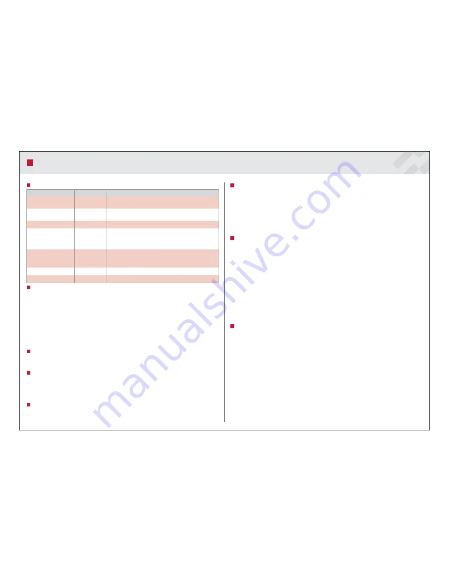
Menu
Setting
Description
Residual oxygen
On/Off
Fan power adjustment according to residual oxygen. The oxygen va-
lue can be seen in the main menu and in the graphic.
Heating circuit
On/Off
Heat regulation of two heating circuits possible. Menu Shunt control
2 is visible, when the sensor is connected.
Tachometer
On/Off
Not in use
Load pump
•
Start
•
Stop
•
Load pump diff
On/Off
0 - 95 °C
0 - 95 °C
0 - 50 °C
Load pump function (tank sensor)
Tank temperature, when burner start ignition
Tank temperature, when burner stops
Load pump goes on, when boiler temp > set temp - Load pump diff
Conv. cleaning
Time On
Time Off
On/Off
3 min (0-10 min)
4 h (0-250 h)
Commissioning of the automatic convection cleaning system and de-
termination of operating times. See page 20.
Smokegasfan Max
30 % (0-100 %)
Flue gas fan power in Power mode.
Smokegasfan Min
0 % (0-30 %)
Flue gas fan power in Maintain mode.


