2/4
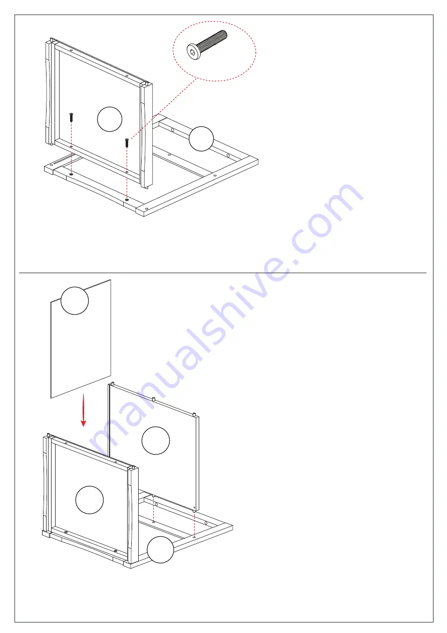
E
D
B
G
x 2
RF10052
Diagram1.
Diagram2.
Step 1.
Attach Bottom (E) to Right Panel (D) by using
Screws (RF10052) as per diagram 1.
Step 2.
Place the shelf (B) and Back Panel (G) to the unit
as per diagram 2.
Page 1: ... Allen Key Hardware 1 4 LIST OF WOODEN PARTS x 2 x 2 x 8 RF10052 Screw JCB M6 x 30 RF44013 Washer RF40002 Spring x 1 x 2 RF40009 Metal Pin x 1 RF40258 Metal Handle A Top B Shelf C Left Panel D Right Panel G Back Panel E Bottom F Door x 1 x 1 x 1 x 1 x 1 x 1 x 1 A B E C D F G ...
Page 2: ...2 4 E D D B G E x 2 RF10052 Diagram1 Diagram2 Step 1 Attach Bottom E to Right Panel D by using Screws RF10052 as per diagram 1 Step 2 Place the shelf B and Back Panel G to the unit as per diagram 2 ...
Page 3: ... Diagram3 Diagram4 Step 3 Attach the Handle RF40258 to the Left Panel C Attach Left Panel C to the unit by using Screws RF10052 as per diagram 3 Step 4 Upright the unit Attach Top A by using Screws RF10052 as per diagram 4 C x 1 RF40258 ...
Page 4: ...n Door F as per diagram Tip Carefully hold the pins to prevent it from bouncing off Insert the pin on top of Door F to the hole on Shelf B first then place the pin on bottom of Door F to Panel E Ensure the top and bottom pins on Door F are inserted into the holes on Panel E E B Tip Carefully hold the pins to prevent it from bouncing off ...