System Installation Manual
Digital Key Telephone System
Arista Systems Corporation
14
28
DV
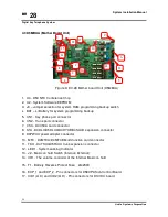
4.3 D5MBUA (Mother Board Unit)
Figure 3: DV-28 Mother board Unit (D5MBUA)
1. U4 - D5CNFC Conference Chip
2. U2 - System Software EEPROM
3. J3 – Jumper selection for system RAM programming backup switch
4.
BAT – Li Battery for system programming backup
5. CN1 - Key phone port connector
6. CN2 - Trunk port connector
7. VSC - D4VSCA card connector
8. STA - D4DLU/D5DLUA/D4HYUB/D4SLUB expansion connector
9. D4PWUA power adapter connector
10. MFC - D4MFCA/D4MFCB Multi-function card connector
11. TKU - D4TKUA/D5TKUA trunk expansion connector
12. LED1 - System working Indicator
13. J2 - Music on hold Switch (Internal/ External)
14. VR1 - The volume controller of the Internal Music on hold
15. F1 - Battery Reverse Protect Fuse
:
2A/250V
16. EXP_1 and EXP_2 - Pin connectors for D5EXPA Sub-Control Board.
17. CID1(A~D) and CID2(A~D) - Pin connectors for D1CIDC board.
1
3
5
7
4
6
8
9
10
13
14
11
15
12
16
17
2
Summary of Contents for DV-28
Page 10: ......


