Arista ARP-3600AP-E01 Series User Manual Download Page 26

26

The AC to DC 24V power supply provided with the ARP-3600AP-E01 Series touch panel 

computer does not have environmental protection. In order to meet a degree of protection, 

the power supply has to be installed in a specific IP rating enclosure. 
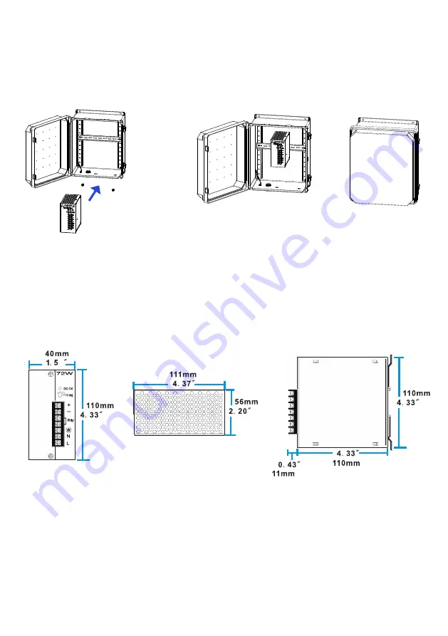
   

Screws

Industrial

Enclosure 

Step1

Step2

Step3

In order to correctly install the power supply, the specific dimensions for the power supply 

are indicated in the diagram below. 

7

48W DIN-rail 

Power supply

Front View

Top View

Side View

Summary of Contents for ARP-3600AP-E01 Series

Page 1: ...y of your new touch panel computer This ARP 3600AP E01 Series touch panel computer is designed to be operated in harsh environments and meet the performance requirements of today s demanding industrial applications The ARP 3600A E01 Series touch panel computer provides auto input synchronization and easy to use interfaces Publication date 2016 03 24 Version No V1 5 USER MANUAL Talk to us We listen...

Page 2: ...ided by the supplier make sure that it is certified by the local and applicable national standards If the power cable is faulty in any way please contact the manufacturer or the nearest authorized repair service provider for a replacement The power supply cord is used as the main disconnect device Ensure that the socket outlet is easily accessible after installation Overloaded AC outlets extension...

Page 3: ...cting to a display 22 Connecting to keyboard or mouse 23 Connecting to network 24 Connecting to the COM port 24 Connecting the power supply 25 Connecting the battery power 27 Installing memory module expansion card 28 Adjustment on touch screen 31 Chapter 4 BIOS Setup 33 Introduction 33 Entering the setup 34 Main Menu 36 Advanced Menu 37 Chipset Menu 44 Security Menu 47 Boot Menu 48 Save Exit Menu...

Page 4: ...s CFAST Card slot MINI PCIE slot the MINI PCIE slot supports Wi Fi function and Solid State Drives SSD SATA DOM 2 5 HDD 2 5 SSD Supports programmable GPIO port 4 bit Input 4 bit Output Two Dual Gigabit RJ45 LAN ports provides high speed and stable network connections Support External Smart Battery power input Panel moutable for better stability Strengthened protective glass anti reflective optiona...

Page 5: ...OM1 GPIO 1 x GPIO port LAN 2 x LAN Dual Gigabit LAN Keyboard Mouse 1x PS2 keyboard 1x PS2 mouse CFAST Card 1 x CFAST Card slot Power 1x DC IN power 1 x Battery power input Operating system OS Support Windows Thin SP3 7 0 Manager Physical information Mounting Panel mounting Physical dimension ARP 3610AP E01 11 50 8 80 4 20 inch 292 224 107 mm L W D ARP 3615AP E01 14 50 11 80 4 36 inch 369 300 111 m...

Page 6: ...carefully to make sure no item is damaged and all items listed are present in your package t ures ARP 3600AP E01 Series touch panel computer Unpacking AC power cable x1 DIN Rail AC DC power supply x1 DC power cable x1 Mounting bolts and screws ...

Page 7: ...7 Product overview Chapter 2 Basics Side Bottom Front ARP 3600AP E01 Series Touch Panel Computer ...

Page 8: ...indicator The LED lights up when you turn on the system and be off when the system is in standby mode HDD LED Hard Disk Activity LED indicator The read or write activities of the hard disk cause the LED to light up 1 2 3 4 5 6 7 8 9 11 10 12 13 1 PS 2 Keyboard connector 8 CFAST card slot 2 PS 2 Mouse connector 9 USB port 3 USB ports 10 Power LED up HDD LED down indicator 4 HDMI port 11 24V DC IN p...

Page 9: ...cal and specific dimensions of the ARP 3600AP E01 Series touch panel computer Physical dimension 268 0mm 10 6 292 1mm 11 5 106 9mm 4 2 50 25mm 2 0 34 5mm 1 4 200 4mm 7 9 140 5mm 5 53 223 5mm 8 8 201 4mm 7 9 33 3mm 1 3 For ARP 3610AP E01 ...

Page 10: ...cal and specific dimensions of the ARP 3600AP E01 Series touch panel computer Physical dimension For ARP 3615AP E01 344 0mm 13 5 368 5mm 14 5 96 1mm 3 8 277 0mm 10 9 140 5mm 5 5 299 8mm 11 8 201 4mm 7 9 71 3mm 2 8 56 5mm 2 22 54 4mm 2 14 ...

Page 11: ...11 For ARP 3617AP E01 377 5mm 14 86 403 4mm 15 88 56 5mm 2 22 59 8mm 2 36 135 0mm 5 32 316 0mm 12 44 140 5mm 5 53 338 8mm 13 34 201 4mm 7 93 88 0mm 3 47 ...

Page 12: ...12 For ARP 3619AP E01 427 0mm 16 81 452 1mm 17 80 56 5mm 2 22 67 1mm 2 64 164 7mm 6 48 345 6mm 13 61 140 5mm 5 53 370 8mm 14 60 201 4mm 7 93 112 8mm 4 44 ...

Page 13: ...13 For ARP 3621AP E01 501 0mm 19 72 533 0mm 20 98 56 5mm 2 22 59 8mm 2 35 127 8mm 5 03 308 7mm 12 15 140 5mm 5 53 330 0mm 12 99 201 4mm 7 93 149 8mm 5 90 ...

Page 14: ...th W Overall width H Overall Height ARP 3610AP E01 11 50 292 1mm 8 80 223 5mm 4 20 106 9mm ARP 3615AP E01 14 50 368 5mm 11 80 299 8mm 4 36 110 9mm ARP 3617AP E01 15 88 403 4mm 13 34 338 8mm 4 58 116 3mm ARP 3619AP E01 17 80 452 1mm 14 60 370 8mm 4 87 123 6mm ARP 3621AP E01 20 98 533 0mm 12 99 330 0mm 4 58 116 3mm ARP 3624AP E01 23 91 607 3mm 14 50 368 3mm 4 51 114 6mm ...

Page 15: ...ctors are located at the bottom of ARP 3600AP E01 Series touch panel computer Chapter 3 Connections This section describes the connections connectors available on the ARP 3600AP E01 Series touch panel computer ...

Page 16: ...S 485 2 RXD Receive data TX Transmit data RS 422 RS 485 3 TXD Transmit data RX Receive data RS 422 4 DTR Data terminal ready RX Receive data ground RS 422 5 GND Signal ground GND Signal ground 6 DSR Data set ready N C 7 RTS Request to send N C 8 CTS Clear to send N C 9 Ring IN Ring indicator N C Note COM1 port is available for RS 232 mode default RS 422 mode or RS 485 Mode ...

Page 17: ... VGA Green signal 3 VGA B VGA Blue signal 4 NC No connection 5 GND Ground 6 GND Ground 7 GND Ground 8 GND Ground 9 NC No connection 10 GND Ground 11 NC No connection 12 CRT DDC Data The data of display data channel 13 VGA HS VGA H Sync signal 14 VGA VS VGA V Sync signal 15 CRT DDC Clock The clock of display data channel 1 ...

Page 18: ... I O_BUS_GPIO3 GPIO input 5 I O_BUS_GPIO4 GPIO output 6 I O_BUS_GPIO5 GPIO input 7 I O_BUS_GPIO6 GPIO output 8 I O_BUS_GPIO7 GPIO input 9 I O_BUS_GPIO8 GPIO output 10 GND Ground GPIO settings Input Ouput I O_BUS_GPIO1 GPIO42 0xFFF240 bit2 I O_BUS_GPIO2 GPIO71 0xFFF270 bit1 I O_BUS_GPIO3 GPIO50 0xFFF250 bit0 I O_BUS_GPIO4 GPIO16 0xFFF210 bit6 I O_BUS_GPIO5 GPIO52 0xFFF250 bit2 I O_BUS_GPIO6 GPIO75 ...

Page 19: ...19 Pins in the DC IN power connector 2 Pin NO Definition 1 GND 2 24V 1 ...

Page 20: ...f ARP 3600AP E01 Series touch panel computer within the place on a board or a wall where the mounting holes are pre drilled And align the mounting bolts installed on the four sides of ARP 3600AP E01 Series touch panel computer with the mounting holes on the wall or board Step1 There are mounting slots located on the four sides of the ARP 3600AP E01 Series touch panel computer As shown in the figur...

Page 21: ...n the M4 sized mounting screws into the wall and board through the mounting bolts and mounting holes and make sure the ARP 3600AP E01 Series touch panel computer is correctly and securely seated onto the board or wall ...

Page 22: ...touch panel computer Connect the other end of the VGA cable to the VGA port of a display 1 Connecting to a display through VGA port HDMI port Display HDMI port HDMI cable not supplied Connect one end of the HDMI to the HDMI port of the ARP 3600AP E01 Series touch panel computer Connect the other end of the HDMI to the HDMI port of a display 2 Connecting to a display through HDMI port ...

Page 23: ...a USB mouse not supplied to ARP 3600AP E01 Series touch panel computer for controlling on the computer Figure 1 You can also insert a PS2 type keyboard or a PS2 type mouse not supplied to your computer Figure 2 Mouse Keyboard Figure 2 ARP 3619AP E01 ARP 3619AP E01 PS2 keyboard jack PS2 mouse jack ...

Page 24: ...eries touch panel computer are designed to make it easy to communicate with other computers and serial hardware As shown in the figure below connect one end of the RS 232 cable to the COM port of the computer Connect the other end of the RS 232 cable to the RS 232 IN connector of a RS 232 peripheral device Like a printer etc LAN port COM port COM1 COM4 LAN port RJ45 LAN cable not supplied ARP 3619...

Page 25: ...ied Connecting the power supply AC outlet Follow the steps below to connect the power supply 8 Important Before you use the power supply please correctly and securely connect the supplied AC power cable to the terminal of L for live wire N for neutral wire and Ground on the power supply and connect the supplied DC power cable to the Power and Ground terminals AC power cable supplied DC power cable...

Page 26: ...order to meet a degree of protection the power supply has to be installed in a specific IP rating enclosure Screws Industrial Enclosure Step1 Step2 Step3 In order to correctly install the power supply the specific dimensions for the power supply are indicated in the diagram below 7 48W DIN rail Power supply Front View Top View Side View ...

Page 27: ...y cable to the Battery power input connector of the ARP 3600AP E01 Series touch panel computer Connect the other end of battery cable to a battery 12V ARP 3619AP E01 Battery not supplied Battery power input connector Note If all the required cable and the power cable are connected correctly the ARP 3600AP E01 Series touch panel computer will be automatically turned on Then the power LED indicator ...

Page 28: ... bottom cover of the ARP 3600AP E01 Series touch panel computer 1 As shown in the figure below remove the screws on the sides of the bottom cover 2 Then remove the bottom cover of the ARP 3600AP E01 Series touch panel computer you will find the DDR3 SO DIMM slot MINI_PCIE1 slot and PCIE x 16 slot The ARP 3600AP E01 Series touch panel computer comes with the B059 motherboard and the DDR3 SO DIMM sl...

Page 29: ...s to remove the DIMM 1 Use your finger to simply push away the retaining clips on both sides of the DIMM outward to unlock the DIMM 2 Then the retaining clip will release and gently remove the DIMM from the module Removing the memory module Note Make sure to unplug the power supply before adding or removing DIMM or other system components Failure to do so may cause severe damage to both motherboar...

Page 30: ...nstalled on the MINI PCIE slot 1 Locate the Wi Fi LAN card on MINI PCIE slot and align the notch on the card with the key on the slot Follow the steps outlined below to install a Wi Fi LAN card 3 Press the Wi Fi LAN card down and secure the card to the B059 motherboard with the screws 2 Insert the card into the slot at 45 degree angle then push it in until the golden finger on the card is deeply i...

Page 31: ...ftware follow the several steps as below 1 Double click the setup to start to install the calibration software 2 Click next to continue and go ahead following the dialog window 3 Restart the computer to finish the installing 4 Now the shortcuts of USB Controller can be found on the desktop ...

Page 32: ...open the USB controller window as below 2 Select the Tools of the eGalaxTouch screen and click the 4 Points Calibration then click OK for video calibration 3 Use the point of something such as the pen to calibrate the four points of the display 4 Once calibrated the touchscreen will be ready to use automatically each time the system is restarted ...

Page 33: ...configure Hard drives diskette drives and peripherals Video display type and display options Password protection from unauthorized use Power Management features The settings made in the Setup Utility affect how the computer performs Before using the Setup Utility ensure that you understand the Setup Utility options The Standard configuration A standard configuration has already been set in the Set...

Page 34: ...U memories etc may also trigger this message When you start the Setup Utility the main menu appears The main menu of the Setup Utility displays a list of the options that are available A highlight indicates which option is currently selected Use the cursor arrow keys to move the highlight to other options When an option is highlighted execute the option by pressing Enter Some options lead to pop u...

Page 35: ...ufacture reserves the right to change the BIOS items presented in this manual The BIOS setup screens shown in this chapter are for reference only and may slightly differ from what you see on your screen Please visit the manufacture s website to download the latest product and BIOS information The BIOS navigation keys are listed below KEY FUNCTION Exits the current menu Enter ESC Scrolls through th...

Page 36: ...u will appear and display the system overview You can set the system clock in this main menu This item shows the current EC information including EC Version System Date Use this item to specify the system date Manually enter the day month and year System Time Use this item to specify the system time Manually enter the hours minutes and seconds Press Esc to return to the Main Menu screen LAN1 LAN2 ...

Page 37: ...hen changing the setting of the Advanced menu items Incorrect field values can cause the system to malfunction ACPI Settings Scroll to this item and press Enter to view the following screen ACPI Sleep State S3 Suspend to RAM UPS Function OFF Select the highest ACPI sleep state the system will resume when the SUSPEND button is pressed Power on or off the Uninterruptible Power Supply UPS system ...

Page 38: ...lowing screen Serial Port1 Port2 Port3 Port4 Configuration Serial port1 port2 port3 port4 Enabled Change settings Auto Type select RS232 Use this option to enable or disable the use of serial ports Select an optimal settings for Super IO device Select serial port type RS232 RS422 RS485 ...

Page 39: ...r to view the following screen Wake system from S5 Disabled Use this item to enable or disable system wake on alarm event Select Fixed Time system will wake on the hr min sec specified Select Dynamic Time system will wake on the current time Increase minute s ...

Page 40: ... information Intel Virtualization Technology Enabled Most of the time hardware virtualization technology extensions should be enabled in motherboard BIOS in order to run recent OS and applications When enabled a VMM can utilize the additional hardware capabilities provided by Vanderpool Technology Press Esc to return to the Advanced Menu screen ...

Page 41: ...nd AHCI SATA Port 0 Enabled Use this item to enable or disable onboard IDE controller The default value is Enabled CFast card Enabled Use this item to enable or disable the use of CFast card The default value is Enabled SATA Port1 2 dynamically detect whether there are SATA devices on motherboard If devices are connected with the corresponding ports then it will display the SATA device type Otherw...

Page 42: ...us Configuration Scroll to this item and press Enter to view the following screen OS selection Windows 7 Use this option to select the operating system for the computer Press Esc to return to the Advanced Menu screen ...

Page 43: ...rt Enabled Use this option to enable USB mouse and USB keyboard support ENABLED option enables legacy USB support AUTO option disables legacy support if no USB devices are connected DISABLED option will keep USB devices available only for EFI applications Press Esc to return to the Advanced Menu screen ...

Page 44: ...ce the features in this section are related to the chipset on the CPU board and are completely optimized you are not recommended to change the default settings in this setup table unless you are well oriented with the chipset features North Bridge Scroll to this item and press Enter to view the following screen Chipset Menu ...

Page 45: ...nt Secondary boot display selection will appear based on your selection VGA modes will be supported only on primary display Select the secondary IGFx video device LCD Panel Type 1920 x 1080 8 bit Dual LVDS This option is used to choose the resolution of the Flat Panel LVDS Enabled Use this item to enable or disable the LVDS video signal output VGA Output Select Forced This option is used to choose...

Page 46: ...d if present disabled otherwise Use this option to configure USB settings XHCI Mode Auto This item allows you to select the mode of operation of xHCI controller Press Esc to return to the Chipset Menu screen Onboard LAN1 LAN2 Enabled Restore AC Power Loss Power on PCI Express Wakeup Enabled This item allows you to enable or disable the onboard LAN1 or LAN2 This item allows you to select AC power s...

Page 47: ... is set then this only limits access to setup and is only asked for when entering Setup If ONLY the user s password is set then this is a power on password and must be entered to boot or enter Setup In Setup user will have administrator rights The password length must be in the following range Minimum length 3 Maximum 20 ...

Page 48: ...is set to On it will automatically activate the Numeric Lock funcition after boot up Quiet Boot Enabled This item allows the bootup screen options to be modified between POST messages or the OEM logo Select Disabled to display the POST messages Select Enabled to display the OEM logo instead of the normal POST messages Fast Boot Disabled This item enables the BIOS to skip certain tests in order to s...

Page 49: ... changes Save Changes Use this item to save the changes made to the BIOS options and reset the system Discard Changes Use this item to exit the system without saving the changes made to the BIOS configuration setup program Restore Defaults This option restores all BIOS settings to the factory default This option is useful if the controller exhibits unpredictable behavior due to an incorrect or ina...

Page 50: ...hips Position your system unit away from direct sunlight moisture dust oil and thoroughfare Do not submit your equipment to harsh jarring Ensure that all ventilation outlets are always free from obstruction To protect components against damage from static electric discharge you should Use a grounding wrist strap The strap will have an alligator clip at the end of a shielded wire lead Clip it to a ...

Page 51: ... Arista Corporation The Limited Warranty does not cover damages and or failures which result from negligence accidents misuse abuse mishandling misapplication alteration faulty installation set up adjustment improper maintenance power surge problems with electrical stability failure to maintain environmental conditions within operating range specified by the manufacturer relocations or attempts to...

Page 52: ... department in 14 calendar days after the product is received Customer can request either return for credit or replacement If replacement is requested Arista will ship the replacement in 7 calendar days and invoice the customer for the replacement A credit memo will be issued to the customer after the DOA product is received and verified Evaluation Return The customer must notify Arista s RMA depa...

Page 53: ... for the RMA product while in transit to Arista We urge customers to pack the RMA product carefully to avoid transit damage Refused Shipment Restocking Fees If a customer refuses a shipment credit will be issued after the refused product is received and verified by Arista The shipping charge plus 15 restocking fees will be billed to the customer 6 RMA Shipping Instruction Product Non Acceptance Pr...

Page 54: ...rporation be held liable for monetary and or non monetary damages resulting from the normal or abnormal usage of our products Use distribution and or similar engagement of our products constitute implied agreement to these and similar Arista Corporation Limited Liability policies Arista Corporation is not liable for damages or reimbursement for lost time lost revenue cost of having someone remove ...

Page 55: ...rs for their personal archival purposes The manufacturer reserves the right to revise this user s manual and all accompanying documentation and to make changes in the content without obligation to notify any person or organization of the revision or change IN NO EVENT WILL THE VENDOR BE LIABLE FOR DIRECT INDIRECT SPECIAL INCIDENTAL OR CONSEQUENTIAL DAMAGES ARISING OUT OF THE USE OR INABILITY TO US...

Page 56: ...Arista Corporation 40675 Encyclopedia Circle Fremont CA 94538 U S A Tel 510 226 1800 Fax 510 226 1890 http www goarista com Talk to us We listen TM ...

Reviews: