


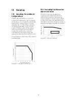

18
6.8
Setting Rest Mode
To extend battery life, the Rest option
can be selected. When reaching the
Float state, the battery will disconnect for
a time frame depending on the battery
type. Throughout this time period, the
voltage on the battery output terminals
will be monitored. Once the voltage
drops below a predefined threshold, the
battery will be reconnected. To enable
this function, place the corresponding
dipswitch to the B position.
Figure 6.8 – Rest Mode setting
Factory setting is Rest Mode OFF. This
corresponds to dip switch n. 6 in position
A
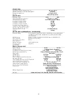
7
Operation Modes
7.1
Standby Mode
This is the default status of the device.
When mains is present and the battery is
present and connected, the device sets
automatically to Standby Mode.
Figure 7.1– Standby Mode
In this mode, load output voltage follows
the battery voltage. Current sharing
between load and battery is
autonomously managed by the device,
always giving priority to load demand.
Signaling
With mains present, the Mains/Backup
LED ( 11 ) will be set on a steady green
color.
Overload and Short Circuit protection
If the load demand increases, taking the
current value up to its short circuit
threshold, the short circuit protection will
trigger. Both Overload and Short circuit
conditions will be shown by the common
FAULT LED and status change of F Relay
output.
7.2
Backup Mode
When the battery is connected and
charged, in case mains either fails, falls
below a threshold value (50% of the rated
input voltage) or is anyhow not present,
the device sets automatically to Backup
Mode. The battery is immediately
connected to the load output, without
any interruption.
Figure 7.2 – Backup Mode
From this moment on, the battery is
entirely in charge of supplying power to
the load. During this mode, load output
voltage will follow battery voltage while it
discharges. The current going to the load
is limited in time according to the
battery status of charge.
Signaling
This condition is shown by a Orange light
on the Mains/Backup LED and a status
change of (M) relay output.
DCU
DC-UPS
BBX
BATTERY BOX
-
BUFFERED
DC LOAD
L/+ N/
–
PE
–
+
–
+
–
+
–
+
Mains
Input
Battery
Output
Load
Output
Summary of Contents for DCU150M1224S
Page 8: ...8 3 3 Dimensions Figure 3 2 Side and front views ...
Page 24: ...24 ...


