Ariens Pro 28 EFI CE Service Manual Download Page 1

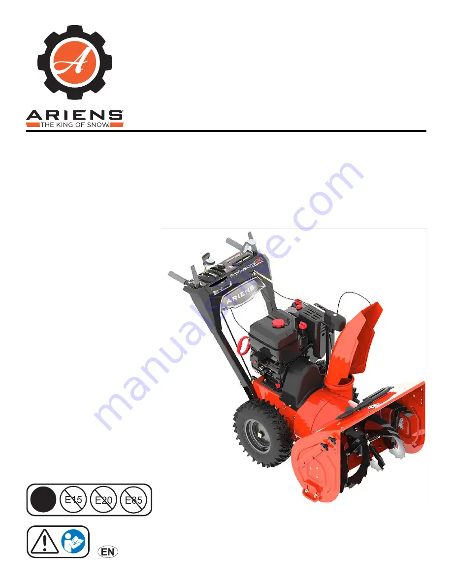
Professional Series Sno-Thro

With Hydrostatic Drive

05136630B • 12/18

 ENGLISH

Models

926060 – Pro 28 RapidTrak

(SN )

926068 – Pro 28 EFI

(SN )

926069 – Pro 32 RapidTrak

(SN )

926070 – Pro 36 EFI

(SN )

926334 – Pro 32 12V CE

(SN )

926336 – Pro 28 EFI CE

(SN )

926337 – Pro 28 EFI CE Track

(SN )

926338 – Pro 28 EFI CE RapidTrak

(SN )

E10

®

Service Guide

Summary of Contents for Pro 28 EFI CE

Page 1: ...926060 Pro 28 RapidTrak SN 000101 926068 Pro 28 EFI SN 000101 926069 Pro 32 RapidTrak SN 000101 926070 Pro 36 EFI SN 000101 926334 Pro 32 12V CE SN 000101 926336 Pro 28 EFI CE SN 000101 926337 Pro 28...

Page 2: ...38 DUAL HANDLE INTERLOCK REPLACEMENT 38 Remove Interlock Cam 38 Install Interlock Cams 39 AXLE BEARING REPLACEMENT 40 Remove Left Axle Bearing 40 Install Left Axle Bearing 40 Remove Right Axle Bearin...

Page 3: ...AriensCo warranty applies solely to defects in AriensCo materials and or factory workmanship AriensCo disclaims liability for any claims or damages whether warranty property damage personal injury or...

Page 4: ...this unit If you loan rent or sell this product to others provide them with all manuals If you have any questions please call our customer support line at 920 756 4688 or contact us at www ariens com...

Page 5: ...erating Keep children out of work area and under watchful care of a responsible adult 08000519B 080000945 Figure 1 3 2 1 Stop engine remove key and read manual before making any repairs or adjustments...

Page 6: ...g engine or hot engine Fill fuel tank outdoors with extreme care Never fill fuel tank indoors Never fill containers inside a vehicle or on a truck or trailer bed with a plastic liner Always place cont...

Page 7: ...is equipped with a spark arrester meeting applicable local state or federal laws A spark arrester if used must be maintained in effective working order by operator Never operate the snow thrower with...

Page 8: ...NOT run engine in an enclosed area Always provide good ventilation Fumes from engine exhaust can cause injury or death Fuel is highly flammable and its vapors are explosive Handle with care Use only...

Page 9: ...position SEPARATE HOUSING FROM FRAME Remove Auger Housing IMPORTANT Save all hardware for reinstallation 1 Stop engine remove key and wait for moving parts to stop and for hot parts to cool 2 Disconne...

Page 10: ...ve anchor from chute control assembly 8 Guide cable end through hole in dash panel IMPORTANT Reinstall hairpin into clevis pin so it is not misplaced 9 Advance to step 13 Generation 3 Chute Control De...

Page 11: ...bushing and hairpin so parts are not misplaced 15 Remove chute deflector cable from J clamp on engine mount See Figure 7 See Figure 8 16 Remove tapping screw securing left side of belt cover to frame...

Page 12: ...starter handle while gently pulling belts from attachment sheave See Figure 11 20 Position support such as a trash can under handlebars so tractor frame remains upright when separated from auger hous...

Page 13: ...n housing mount brackets with holes in frame and reinstall two tapping screws but DO NOT tighten IMPORTANT Unit must be on a flat level surface during steps 6 8 5 Check tire pressure and adjust if nec...

Page 14: ...all belt cover and secure left side with tapping screw Position right side under tapping screw and tighten 12 Insert hex rod end without ears into dash panel until opposite end clears chute gear 13 Po...

Page 15: ...install chute deflector cable into J clamp on engine mount 23 Reinstall deflector cable anchor into deflector bracket 24 Remove sleeve bushing and hairpin from deflector arm and reinstall cable eyelet...

Page 16: ...d advance to step 7 Refer to Operator s Manual See Figure 18 Models 926060 926069 926338 See Figure 19 5 Remove hardware securing height adjuster plate to height adjuster bracket 6 Move height adjuste...

Page 17: ...Align slot with top hole in height adjuster bracket IMPORTANT Align one of the three notches in height adjuster with lock finger to hold adjuster position 4 Reinstall carriage bolts through height adj...

Page 18: ...ttachment drive clutch See Operator s Manual for adjustment procedure NOTICE Check all adjustments after first use TRACTION DRIVE BELT REPLACEMENT Remove Traction Drive Belt IMPORTANT Save all hardwar...

Page 19: ...irst use DRIVE IDLER ASSEMBLY REPLACEMENT Remove Attachment Drive Idler Assembly IMPORTANT Save all hardware for reinstallation 1 Stop engine remove key and wait for all moving parts to stop and for h...

Page 20: ...bly See Remove Attachment Drive Idler Assembly on page 17 See Figure 28 4 Remove hairpin and flat steel washer from traction drive idler arm 5 Remove traction drive cable from idler arm See Figure 29...

Page 21: ...ction drive idler arm and secure with original flat steel washer and hairpin 5 Reinstall attachment drive idler assembly See Install Attachment Drive Idler Assembly on page 19 Install Attachment Drive...

Page 22: ...From Frame on page 7 See Figure 35 4 Disconnect extension spring from frame 5 Remove hardware retaining attachment brake arm to brake mount bracket 6 Remove attachment brake arm Install Attachment Br...

Page 23: ...ll bottom cover and secure with two tapping screws and four hex bolts 8 Return unit to operating position 9 Reconnect spark plug wire and fill fuel tank IMPORTANT Check all adjustments after first use...

Page 24: ...and remove belt finger See Figure 39 7 Remove traction drive belt 8 Remove hairpin and flat steel washer retaining traction drive cable end to traction idler arm Remove cable end from arm See Figure 4...

Page 25: ...d remove shroud See Figure 43 13 Remove hairpin and flat steel washer securing shift rod to transaxle See Figure 44 14 Remove hairpin securing shift rod to bell crank at unit rear and remove shift rod...

Page 26: ...rdware securing transaxle to transaxle mount See Figure 47 See Figure 48 18 Tilt transaxle so tension is removed from chain and remove chain from transaxle 19 Remove transaxle 20 Remove E ring pinion...

Page 27: ...side of chain should have an equal amount of links tension between pinion sprocket and pinion gear If tension is uneven manually turn pinion gear toward side with greater tension until equal See Figu...

Page 28: ...hers and two hex nuts but DO NOT tighten hardware 9 Check chain tension and adjust if necessary See Check Chain Tension on page 28 and Adjust Chain Tension on page 28 10 Tighten hardware if chain tens...

Page 29: ...ey onto hex bolt and secure with one flat steel washer and locking nut 17 Reinstall traction drive belt See Install Traction Drive Belt on page 17 18 Reinstall housing to frame See Reinstall Auger Hou...

Page 30: ...ring transaxle to transaxle mount 6 Perform steps 13 21 of Install Transaxle on page 25 and see Check Chain Tension on page 28 Repeat chain adjustment if necessary TRANSAXLE SERVICE Add Transaxle Flui...

Page 31: ...unit lowers to the ground Remove jack If unit drives normally no further adjustment is needed If drive malfunctions continue to steps 7 10 7 Wait for all moving parts to stop and for hot parts to coo...

Page 32: ...tall shaft into transmission bracket and position bearing flanges outside transmission bracket 3 Secure each bearing flange to transmission bracket with 3 tapping screws 4 Install sleeve bushing onto...

Page 33: ...bearing plate to auger housing 6 Remove hardware retaining support bushings to auger housing See Figure 64 7 Remove auger assembly from housing See Figure 65 See Figure 66 IMPORTANT Flange bushing is...

Page 34: ...nd 5 Align holes in auger with holes in auger shaft and reinstall shear bolt Torque bolt to 7 9 N m 16 5 N m 5 8 lb ft 12 2 lb ft If torque wrench is unavailable tighten until bolts no longer spin fre...

Page 35: ...key and wait for all moving parts to stop and for hot parts to cool 2 Disconnect spark plug wire from engine 3 Remove augers See Remove Auger on page 31 See Figure 70 4 Remove two flat steel washers f...

Page 36: ...penetrating oil or heat may be necessary to remove impeller Install Impeller 1 Install impeller onto impeller shaft and align with holes in impeller with holes in impeller shaft Reinstall roll pins 2...

Page 37: ...e onto crankshaft Secure with spacer bushing locking washer and hex bolt 3 Using a suitable lifting device or adult assistant lift engine over frame and tilt slightly forward so belts reach over engin...

Page 38: ...ttery terminal 5 Remove battery Install Battery 1 Install battery in battery tray so negative terminal is positioned on the right side from perspective of the operator in operator s position 2 Reconne...

Page 39: ...See Service Position on page 7 and Remove Bottom Cover on page 14 7 Remove hardware securing upper traction clutch cable to clutch lever and remove cable See Figure 79 See Figure 80 8 Remove upper tra...

Page 40: ...airpin See Figure 78 8 Tighten shoulder bolt securing cable pulley to pulley bracket 9 Return unit to operating position 10 Reinstall belt cover and secure left side to frame with one tapping screw Po...

Page 41: ...am onto camshaft so flat edge is positioned downward Secure with spring clip See Figure 85 See Figure 86 3 Position left interlock cam inside interlock bracket and align with left camshaft 4 Insert ca...

Page 42: ...stall bottom cover and secure with two tapping screws and four hex bolts 5 Reinstall wheel and secure with snap clip 6 Return unit to operating position 7 Reconnect spark plug wire and fill fuel tank...

Page 43: ...ght Axle Bearing 1 Align bearing with bearing plate and mount to frame with three hex bolts from inside frame Secure with three locking nuts See Figure 91 IMPORTANT Make sure sleeve bushings remain in...

Page 44: ...ove bottom cover See Service Position on page 7 and Remove Bottom Cover on page 14 4 Models 926060 926069 926338 Advance to step 8 Model 926337 Advance to step 12 Models 926068 926070 926336 5 Remove...

Page 45: ...will fall when pinion shaft is removed 11 Advance to step 14 Model 926337 12 Remove drive wheels and tracks from unit See Remove Track Drive Wheel on page 60 See Figure 96 13 Remove two spring clips f...

Page 46: ...o pinion gear IMPORTANT Make sure pinion gear is aligned with chain and differential gear 4 Models 926068 926070 926334 926336 926337 Position spacer between pinion gear and frame Models 926060 926069...

Page 47: ...nk and reconnect spark plug wire DIFFERENTIAL GEAR REPLACEMENT Remove Differential Gear IMPORTANT Save all hardware for reinstallation 1 Stop engine remove key and wait for all moving parts to stop an...

Page 48: ...ion gear and short axle and reinstall axle into differential See Figure 107 4 Reinstall long axle into differential gear 5 Reinstall E ring onto axle end 6 Reinstall bottom cover and secure with origi...

Page 49: ...Support discharge chute so it remains upright 6 Remove hardware securing chute rotation gear to pedestal plate and remove chute gear Install Chute Rotation Gear IMPORTANT Make sure discharge chute is...

Page 50: ...engine remove key and wait for all moving parts to stop and for hot parts to cool 2 Disconnect spark plug wire from engine 3 Remove chute rotation gear See Remove Chute Rotation Gear on page 47 4 Rem...

Page 51: ...ing and align with holes in housing 2 Insert five flat head square neck bolts through scraper blade from inside housing Secure with five top locking flange nuts 3 Insert two round head square neck bol...

Page 52: ...5 Disconnect wire harness from bulb 6 Turn bulb one eighth turn counterclockwise and remove from headlight bezel See Figure 116 Install Bulb IMPORTANT DO NOT touch new bulb with bare hands wear gloves...

Page 53: ...ngine 3 Disconnect wire harnesses from ECU 4 Remove hardware retaining ECU bracket and remove bracket See Figure 117 See Figure 118 5 Disconnect wire harness from battery connector 6 Remove hardware r...

Page 54: ...NE CONTROL UNIT ECU Models 926068 926070 926336 926337 926338 Remove ECU IMPORTANT Save all hardware for reinstallation 1 Stop engine remove key and wait for all moving parts to stop and for hot parts...

Page 55: ...esses to ECU 4 Reconnect spark plug wire GEARCASE REBUILD Disassemble Gearcase IMPORTANT Save all parts for reassembly unless otherwise specified 1 Remove gearcase See Remove Gearcase Assembly on page...

Page 56: ...from gearcase See Figure 126 See Figure 127 7 Press auger shaft through the right side of gearcase NOTICE DO NOT strike auger shaft end use a press 8 Remove seal bushing and washer from auger shaft 9...

Page 57: ...il shaft is through front of gearcase NOTICE DO NOT strike impeller shaft end without using a driver 12 Remove pin and bushing from impeller shaft 13 Remove impeller shaft from gearcase and remove all...

Page 58: ...er orientation 3 Install gear into gearcase See Figure 134 4 Reinstall impeller shaft through gearcase front and reinstall thrust collar onto impeller shaft end 5 Wrap a seal protector around impeller...

Page 59: ...pin 8 Move impeller shaft as far through gearcase rear as possible 9 Reinstall flange bushing onto impeller shaft end With a driver strike bushing until positioned just below retaining ring groove Se...

Page 60: ...ositioned toward gearcase 15 With a driver such as a 1 1 4 deep well socket drive bushing into gearcase until groove is just beyond interior gearcase wall See Figure 140 See Figure 141 16 Wrap seal pr...

Page 61: ...e oil Oil level MUST be 6 1 cm 6 7 cm 2 4 2 6 from the flat surface of the gearcase cover IMPORTANT Ariens recommends using only Ariens L3 synthetic sever duty gear lube Using other lubricants will no...

Page 62: ...2 Align track drive wheel with track center and secure to axle with snap ring 3 With help from an adult assistant pull up on rear track axle so eye bolts insert through tension brackets Secure with ce...

Page 63: ...tional and MUST be installed in the orientation shown in Figure 150 and Figure 151 1 Install track onto carriage assembly and align with bogie wheel s and track runner if applicable 2 Reinstall track...

Page 64: ...k on page 61 5 Remove hardware retaining bogie wheels to rear track axle and remove wheels See Figure 152 Install Bogie Wheel 1 Install bogie wheel onto track axle and secure with hex nut but DO NOT o...

Page 65: ...igure 154 6 Remove E ring from right axle end 7 Models 926060 926069 926338 Remove hubs from axle ends Model 926337 Remove flat steel washers from axle ends 8 Remove long axle from differential gear S...

Page 66: ...between bearings See Figure 158 and Figure 159 3 Insert stepped down end of long axle through carriage frame and into differential gear 4 Models 926060 926069 926338 Reinstall hub onto each axle end M...

Page 67: ...Disconnect spark plug wire from engine 3 Place unit in service position See Service Position on page 7 4 Remove track drive wheel and remove track See Remove Track Drive Wheel on page 60 and Remove T...

Page 68: ...0 926069 926338 See Figure 163 IMPORTANT Flat steel washers will become free when short axle is removed 10 Hold differential gear and remove short axle IMPORTANT Make sure sleeve bushings remain insid...

Page 69: ...NOT installed with bearing on carriage 1 Secure each bearing to frame and or carriage with three hex bolts and three locking nuts 2 Reinstall sleeve bushing between frame and carriage bearings See Fi...

Page 70: ...e 10 Reinstall bottom cover and secure with four hex bolts and two tapping screws Tighten hardware 11 Reinstall track drive wheel and reinstall track See Install Track Drive Wheel on page 60 and Insta...

Page 71: ...ensor 75 Code 22 Engine Temperature Sensor 75 Code 23 EFI System Cannot Sustain Desired RPM 75 Code 27 Low Fuel Pressure 75 Code 28 High Battery Voltage 77 DIAGNOSTICS FOR NON TROUBLE CODES 77 Engine...

Page 72: ...by Parts Radar link at www ariensco com for replacement part numbers of the items listed below ECU Barometric Pressure Sensor Air Temperature Sensor Throttle Body Assembly Throttle Plate Servo Motor F...

Page 73: ...throttle plate See Figure 173 Figure 172 Throttle Body Assembly Fuel Pump With Internal Filter Engine Temperature Sensor Inline Fuel Filter Figure 173 Fuel Inlet Fuel Pressure Sensor Internal Servo Mo...

Page 74: ...cement See EFI Trouble Code Identification on page 73 Visually inspect the red LED to verify trouble codes To read trouble codes more easily place a mirror under the ECU to view LED reflection IMPORTA...

Page 75: ...age measures less than 7 5 V DC check charging system at the engine Advance to step 5 IMPORTANT If the engine is cold it is normal for the engine speed to be 100 RPM 200 RPM higher until operating tem...

Page 76: ...rs If wires are disconnected repair or replace wire harness b If connections are in good condition disconnect and reconnect wire harness and recheck voltage Voltage should read 11 5 V AC 14 V AC c If...

Page 77: ...See Figure 183 If voltage measures less than 7 2 V DC check the battery voltage by probing the green wire on the ECU 12 pin connector See Figure 184 If low voltage or no voltage is present replace th...

Page 78: ...in the AC output wire from the stator to the ECU Other possible causes may include an ECU or engine charging system failure 1 Check wire harness connection to the ECU a With the ignition key in the of...

Page 79: ...th battery voltage between 7 2 V DC 8 4 V DC check if the green ECU status light is blinking at a consistent rate IMPORTANT If battery measures below 7 2 V DC ECU LEDs may appear dim or will not illum...

Page 80: ...assembly c If no voltage is present at the injector check battery voltage by probing the red and white wires on the 12 pin ECU connector with the red probe and contact the black probe against the eng...

Page 81: ...ut a Remove the heater box b Check voltage at fuel pump See Code 27 Low Fuel Pressure on page 75 for voltage readings c Remove fuel hose from fuel pump outlet and attach a suitable length of fuel hose...

Page 82: ...wire should measure close to 0 01 V DC at low idle and close to 5 0 V DC at full throttle If voltage does not vary between low idle and full throttle replace the ECU If voltage varies at both termina...

Page 83: ...EN 82 SERVICE RECORD DATE SERVICE COMPLETED NOTES...

Page 84: ...655 West Ryan Street Brillion WI 54110 www ariensco com parts ariens com PRINTED...

Reviews: