Argon 18 E-119 TRI Assembly Manual Download Page 40

39

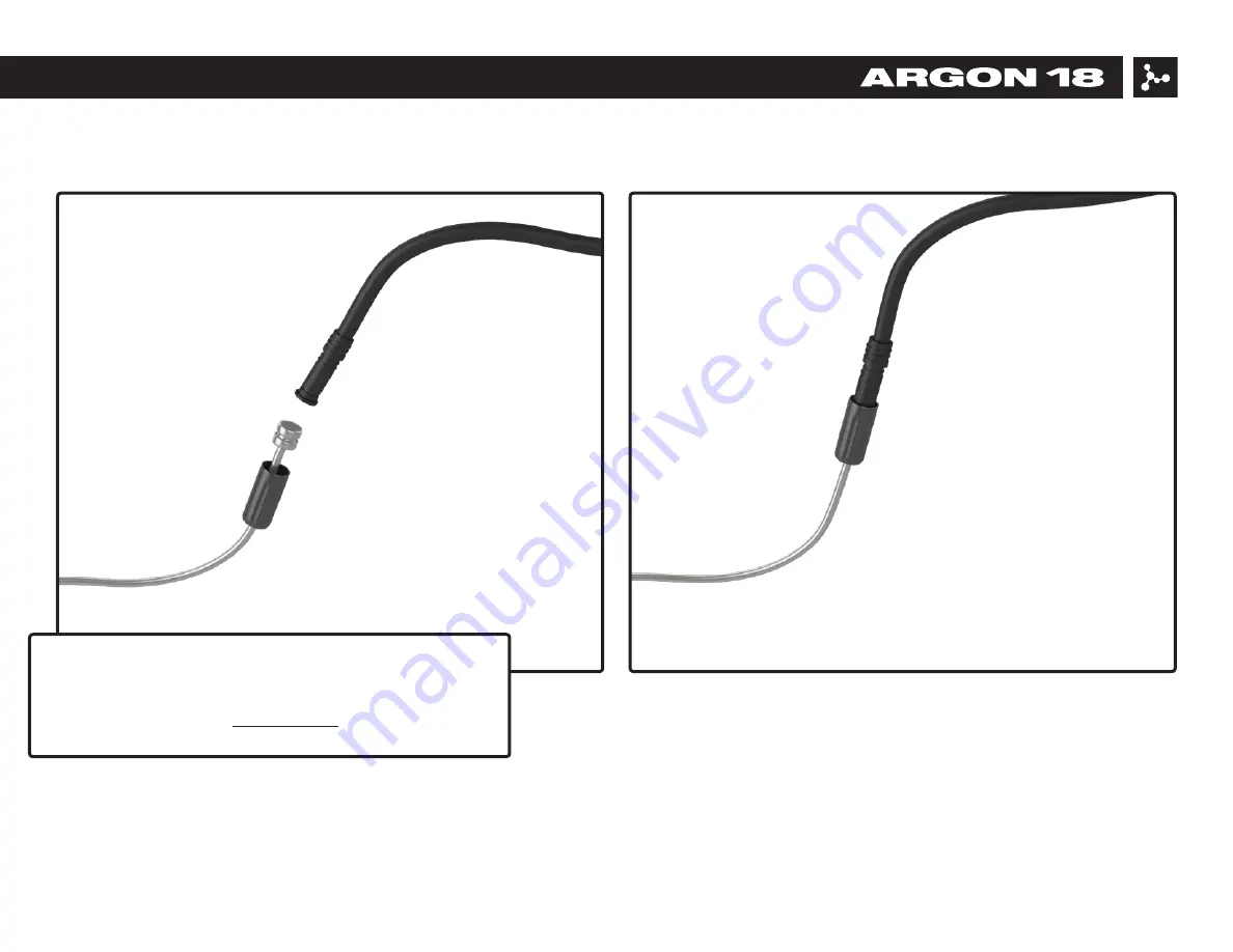
The Di2 cable routing can be achieved easily using this 

simple trick: use a gear cable and a metal cable end to fix the 

Di2 cable.  For more information on Shimano Di2 electronic 

system installation, go to: si.shimano.com.

E-119 TRI 233A: 13. Electronic Drive-train Specification

Summary of Contents for E-119 TRI

Page 1: ...E 119 TRI 233A ASSEMBLY GUIDE Valid for MY2016 E 119 Tri Revision 14 0 07 17 2019...

Page 2: ...c Drive train Specification 38 14 Armrest Installation 41 15 Saddle Adjustment 42 16 Troubleshooting Tips 43 17 Parts SKUs and Descriptions 44 For the warranty to be valid the bicycle must be fully as...

Page 3: ...42 or 243 11 Torque Wrench Hex bit 12 Long nose Plier First Aid Kit Essential parts to always have on hand IN CASE OF EMERGENCY THIS MIGHT SAVE YOUR RIDE 1 Spare rear dropout SKU 38883 2 Spare brake p...

Page 4: ...1 7 52 7 52 7 52 7 52 7 52 7 54 5 52 7 54 5 54 5 54 5 54 5 54 5 580 580 580 580 580 580 580 590 580 590 590 590 590 590 605 605 605 605 605 605 630 630 630 630 630 658 630 658 658 658 658 658 480 480...

Page 5: ...0279 80282 80277 80080 38977 80061 80158 80492 80165 80341 80160 80280 80295 80303 80308 80281 80159 80297 80292 80293 36165 38975 80298 39000 SP E119T 233A 38883 38882 80167 80022 80023 80077 80629 8...

Page 6: ...he seatpost to the desired height 4 Apply a drop of blue Threadlocker n 242 on the bolt s thread 5 Tighten the set screw at max 5 5Nm while leaving a space between the two parts allowing them to slide...

Page 7: ...mp B 3 Slide saddle clamp B onto rocker C 4 Tighten the bolt up at 12Nm See p 42 for saddle adjustment IMPORTANT The E 119 Tri s saddle rail clamp is made for aluminum and round shaped saddle rails Fo...

Page 8: ...7 E 119 TRI 233A 5 Seat Post Installation The Di2 battery is hidden in the seatpost use the Di2 battery holder 3 2 to fix the battery correctly Apply a slight amount of grease on both parts GREASE GRE...

Page 9: ...IMPORTANT The following parts are assembled on the frame When assembling the bike you will need to adjust these parts according to their torque specifications BEFORE ASSEMBLING YOUR NEW E 119 TRI MAK...

Page 10: ...Adjustment 1 Ensure that the dropout is aligned 2 Use Derailleur Hanger Alignment Gauge like ParkTool Item DAG 2 For any assistance visit ParkTool s website parktool com product derailleur hanger ali...

Page 11: ...ment The front derailleur hanger can be adjusted according to the front derailleur angle in order to get an equal curve between the derailleur and the big chainring Once at the right angle use blue 24...

Page 12: ...ion 11 1 Install bearings MR136 1 5 5 and MR122 1 1 8 5 6 inside the frame after greasing the surfaces 2 Install the fork by placing the lower part first and then balancing the upper part in its final...

Page 13: ...ad tube The threads must be lightly greased until the compression column can be inserted smoothly and tightly Use the 3d headset tool provided 5 8 5 Make sure the fork doesn t have any side play and t...

Page 14: ...E 119 TRI 233A 9 Front Brake Installation 13 Exploded view of the front brake 2 5Nm 2 5Nm GREASE GREASE 2 9 2 1 5 3 7Nm 7Nm 2mm washer Brake wedge...

Page 15: ...housing length A FRONT brakes CGX 5mm 32cm B1 REAR brakes grey E Z Bend Handlebar Section 40cm B2 REAR brakes KEB 5mm Frame Section 70cm C FRONT derailleur LEX 4mm 120cm D1 REAR derailleur LEX 4mm Fra...

Page 16: ...th spring stopper facing inward Once brake arms are fixed rotate them in order to have spring stopper pin facing outward 2 Choose the desired position of the handlebar high 2 5cm or low 2 5cm For easi...

Page 17: ...lever and route it so it comes out the middle section underneath of the bar 8 Install a short cap A to the housing at the fork section The short 12mm cap is not included with the bike do not use long...

Page 18: ...le install the handlebar on the fork Apply a dab of grease on all bolts 4 13 and tighten to 6Nm in an alternate way 11 While still pulling on the cable test the brake lever function to make sure that...

Page 19: ...on 14 To secure cable pre tighten cable clamp bolt with 8mm flat wrench Avoid moving the wedge on the cable and remove the wedge from the brake arms 15 Using a 13mm flat wrench to hold the wedge in pl...

Page 20: ...re not to fray the cable s end 18 Thread cable end through cable clamp bolt and pull tight with pliers Add cable crimp 19 Replace wedge between brake arms and make sure that rollers are in home positi...

Page 21: ...1mm 28mm 2mm 25 32mm 2mm 2mm 28mm 2mm 25 max 32mm 2mm 2mm Notes 1 Never adjust pad clearance lower than 2mm pad to rim distance on each sides 2 Spare1 5mm brake pad washer included for extra adjustmen...

Page 22: ...andlebar Installation 21 Install vertical spacers 4 3 and two sleeve nuts 4 8 See next page for stack configuration options 4 8 4 1 4 3 4 12 1 GREASE 4Nm 4Nm 4Nm 4Nm CARBON FIBER ASSEMBLY PASTE 4 21 G...

Page 23: ...e nut 50mm 50mm 50mm 50mm 50mm 80mm 80mm Screw flat head 25mm 25mm 35mm 35mm 45mm 15mm 25mm Total stack height mm 70 75 80 85 90 95 100 WITH SWIVEL Required spacer 10 40 X 20 40 5 20 40 70 5 70 10 70...

Page 24: ...nscrewed just enough to allow adjustment and to turn the swivel 90 degrees in order to have access to the sleeve nuts 4 8 and fix the socket head screw at 4Nm Tighten swivel screw 4 2 4 to 8Nm Note Th...

Page 25: ...n insert them through the notches at the center of the spacers Make sure the Di2 cable goes through the bottom notch Drop the cable in the handlebar using the hole between the two sleeve nuts Run the...

Page 26: ...mm in length The cut must be made on the elbow side The other end of the bar is used exclusively to install the shifter Apply some carbon fiber assembly gel in the clamping area If using a ski bend se...

Page 27: ...E 119 TRI 233A 11 Rear Brake Installation 26 Exploded view of rear brake 5Nm 7Nm GREASE 1 2 1 3 1 18 5Nm GREASE 7Nm 5 4...

Page 28: ...ine if there is a need for a metal cap at the lever e g Shimano no TRP yes 2 Measure approx 400mm length of the gray E Z Bend housing so the handlebar rotates without restrictions 3 Install the brake...

Page 29: ...o avoid cable friction 7 Connect the E Z Bend handlebar section to the frame KEB section of housing with cable jointer 8 Insert the housing inside frame and so it by passes the bottom bracket guide an...

Page 30: ...s bottom of brace 13 Push housing inside frame while holding on to the cable and thread cable into brake brace cable stop hole 14 Gently insert brakeset into frame opening careful not to kink cable 15...

Page 31: ...the brake lever function to make sure that the housing is well seated and that there is no cable friction 18 Make sure brake arms can loosely rotate 19 With pliers tightly pull on cable end and secure...

Page 32: ...Rear Brake Installation 31 outer side 21 Push cable end under cam retention pin depress brake lever to rotate cam upward to ease this operation 22 Re install tension spring between brake arms with lon...

Page 33: ...d ferules are well seated in cable stops insert something hard between brake pads e g plier s handle and apply force on brake lever If cable tension is lost unscrew cable clamp bolt and retighten 25 I...

Page 34: ...25 7mm 3 6mm 2 5mm 28mm 2x 2mm N A N A N A N A Notes 1 Max plunger extension length A is 10 5mm or when back end is flush with brake arm head 2 Resulting pad clearance is measured from center of brak...

Page 35: ...en the two housing lengths Suggested lengths of the cable housing inside the frame medium frame is used as a reference Cable housing length A FRONT brakes CGX 5mm 32cm B1 REAR brakes grey E Z Bend Han...

Page 36: ...ns FD front derailleur RD rear derailleur NOTE The rear brake RB is not used The cable housing is internaly routed to the rear brake 3 Thread cable housing through frame starting from triangular openi...

Page 37: ...e the cable to the rear exit at the drive side chain stay 7 Insert cable stop 1 11 into cable exit hole install 18cm cable housing length and into rear derailleur 8 Install bottom bracket cover 1 10 t...

Page 38: ...Once all cables are routed place the stem cap 2 4 using the screws 2 5 and 2 10 Torque screw to 1Nm 37 E 119 TRI 233A 12 Cable Housing Installation Gears 2 4 2 10 2 5 2 10 1Nm...

Page 39: ...cable section that runs through the drive side chainstay use the preinstalled tube guide that is supplied with the frame Use the proper cable stopper or grommet to fix the rear derailler cable correct...

Page 40: ...ved easily using this simple trick use a gear cable and a metal cable end to fix the Di2 cable For more information on Shimano Di2 electronic system installation go to si shimano com E 119 TRI 233A 13...

Page 41: ...ommet on the top tube to fix the cable correctly depending if you use mechanical drive train 1 9 or electronic shifting 1 8 1 9 1 8 Rear derailleur Front derailleur E 119 TRI 233A 13 Electronic Drive...

Page 42: ...4 and 4 12 5 2 Screw the armrests into the extension bar connector bridge 4 12 2 at 5Nm in the desired position Reverse the left and the right armrests to obtain a more forward or backward setup 3 Fin...

Page 43: ...all saddle rails into the rocker in the middle position 4 Find desired setback 5 Tighten the 5mm bolt up at 6Nm 6 Adjust seat horizontally 7 Tighten the 6mm bolt up at 12Nm If you are unable to find t...

Page 44: ...ur saddle rails are not round and made of aluminum please refer to Ritchey s part numbers These parts are not sold by Argon 18 but available on Ritchey s website ritcheylogic com 4 HT protector A prot...

Page 45: ...er incl screws Frame 80159 1 1 11 Rear Derailleur Cable Stopper Frame 80160 1 1 17 Front Derailleur Cable Grommet Frame 80264 1 1 19 Head Tube Protector Frame 80495 2 1 20 Rear Derailleur Grommet Fram...

Page 46: ...nector Top Plate Handle Bar 80296 1 4 12 3 Extentsion Bar Handle Bar 80061 2 4 12 4 Left Armrest Handle Bar 80077 1 4 12 5 Right Armrest Handle Bar 80078 1 4 12 6 Computer Mount Handle Bar 38975 1 Set...

Page 47: ...1 Set 5 2 Vision TriMax Aero Brake Levers Handle Bar 39108 1 Set 5 3 Argon 18 Front Brake Assembly Fork 80022 1 5 4 Argon 18 Rear Brake Assembly Frame 80023 1 5 5 MR136 Top Bearing Fork 80650 1 5 6 MR...

Reviews: