11
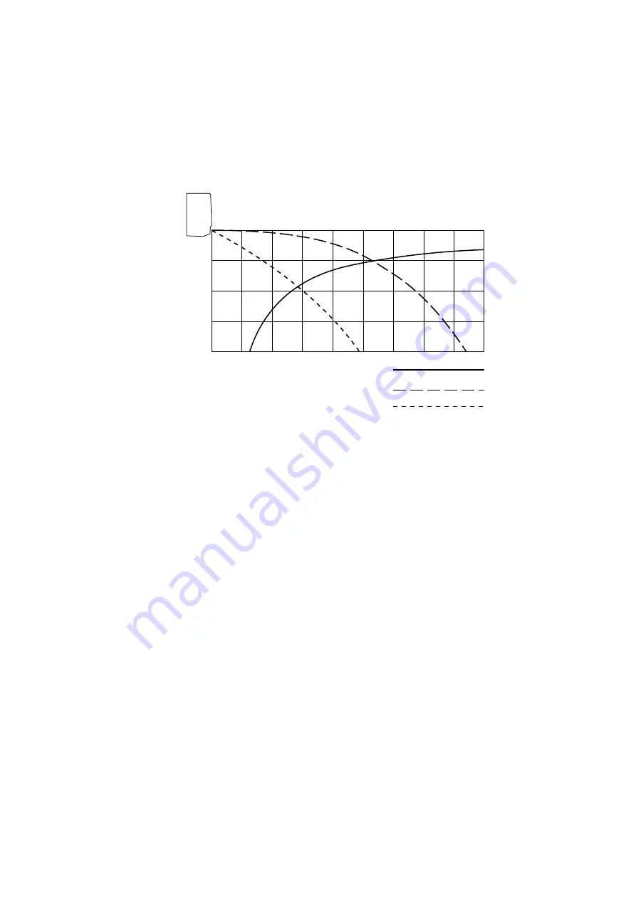
5-2. Air Throw Distance Chart
Indoor Unit AWR218CLE
1
2
3
4
5
6
7
8
9
0
Horizontal distance (m)
Vertical distance (m)
Axis air velocity (m/s)
Room air temp.Fan speed
27
°
C
High
::
Axis air velocity
Louver angle
30
Page 1: ...7 1 6 59 0 18 63 7 6 67 0 5 21 7 21 5 AWR218CLE AER218SC 0 8180 028 0 05 99...
Page 2: ...WARNING When Transporting Be careful when picking up and moving the indoor and outdoor units Get a partner to help and bend your knees when lifting to reduce strain on your back Sharp edges or thin al...
Page 3: ...ubleshooting 19 8 2 Air conditioner does not operate 20 8 3 Some part of air conditioner does not operate 24 8 4 Air conditioner operates but abnormalities are observed 26 8 5 If a sensor is defective...
Page 4: ...1 1 OPERATING RANGE Temperature Indoor Air Intake Temp Outdoor Air Intake Temp Cooling Maximum 32 C D B 23 C W B 43 C D B Minimum 19 C D B 14 C W B 19 C D B For COOLING ONLY models AER218SC...
Page 5: ...Airflow direction Indoor Horizontal Manual Vertical Auto Air filter Washable Anti Mold Compressor Rotary Hermetic Refrigerant Amount charged at shipment g R407C 1 915 Refrigerant control Capillary tu...
Page 6: ...560 Nominal output W 20 Coil resistance Ambient temp 20 C WHT BRN 163 7 WHT VLT 68 8 VLT YEL 33 2 YEL PNK 117 3 Safety Type Internal type devices Operating temp Open C 130 8 Close Automatic reclosing...
Page 7: ...g Operating amp Ambient temp 25 C Run capacitor F 40 0 VAC 400 Type Propeller Q ty Dia mm 1 400 Fan motor model Q ty SG6S 51B5P 1 No of poles rpm 230 V 6 910 Nominal output W 50 Coil resistance Ambien...
Page 8: ...4 20 C 6 3 4 40 C 2 7 4 25 C 5 0 4 50 C 1 8 4 Thermistor Coil sensor TH1 PBC 41E S4 Resistance k 20 C 40 1 5 20 C 6 5 5 10 C 24 4 5 30 C 4 4 5 0 C 15 3 5 40 C 3 0 5 10 C 9 9 5 50 C 2 1 5 Transformer T...
Page 9: ...ermostat Fan Speed Control 23S MQT5S 27YZJ Switching temp C high LOW 23 5 C 1 5 low HIGH 27 0 C 0 3 Contact rating AC 220V 3A Power Relay PR G7L 2A TUB Coil rating AC 200 240V 50 60Hz Coil resistance...
Page 10: ...TA Indoor Unit AWR218CLE Unit mm 1000 360 205 74 61 49 64 Rear panel center point of gravity Drain hose 26 Narrow tube 6 35 1 4 Wide tube 12 7 1 2 Center of tubing hole for right rear Remote control u...
Page 11: ...mm Air discharge Air intake 538 146 307 337 4 12 holes 199 308 706 105 2 6 0 Holes 2 3 5 Extruded holes 830 19 630 380 357 380 146 305 61 95 Wide tube service valve 12 7 1 2 Narrow tube service valve...
Page 12: ...E Outdoor Unit AER218SC Compressor Accumulator Wide tube service valve Wide tube O D 12 7 mm 1 2 Narrow tube service valve Narrow tube O D 6 35 mm 1 4 Condenser Capillary tube Capillary for liquid inj...
Page 13: ...C Outdoor fan speed High Low 1 1 10 1 0 9 0 9 8 0 8 7 0 7 6 Low pressure at wide tube service valve MPa kgf cm 2 G 0 6 5 0 5 4 0 4 3 0 3 2 0 2 1 0 1 0 32 27 21 32 27 21 Points of Rating condition Bla...
Page 14: ...ir Throw Distance Chart Indoor Unit AWR218CLE 1 2 3 4 5 6 7 8 9 0 1 2 3 4 Horizontal distance m Vertical distance m Axis air velocity m s Room air temp Fan speed 27 C High Axis air velocity Louver ang...
Page 15: ...31 SHC 4 70 4 59 4 45 4 15 TC 5 36 5 10 4 79 4 41 CM 2 01 2 16 2 28 2 38 21 SHC 2 36 2 24 2 11 1 94 19 23 SHC 2 74 2 63 2 49 2 33 25 SHC 3 13 3 01 2 88 2 71 27 SHC 3 51 3 40 3 26 3 10 29 SHC 3 90 3 78...
Page 16: ...0 Power Input kW 0 062 0 072 0 082 0 091 2 056 2 157 2 20 2 32 Full Load Conditions Running Amps A 0 28 0 30 0 40 0 42 11 32 10 79 12 0 11 5 Power Input kW 0 062 0 072 0 082 0 091 2 486 2 517 2 63 2...
Page 17: ...14 6 2 Electric Wiring Diagrams To avoid electrical shock hazard be sure to disconnect power before checking servicing and or cleaning any electrical parts WARNING Indoor Unit AWR218CLE...
Page 18: ...15 To avoid electrical shock hazard be sure to disconnect power before checking servicing and or cleaning any electrical parts WARNING Outdoor Unit AER218SC...
Page 19: ...pressure the control circuit has a built in automatic time delay to allow the internal pressure to equalize As a protective measure the control circuit switches the compressor OFF after 5 minutes or...
Page 20: ...l falls below 1 C the control circuit stops the compressor for at least 6 minutes The compressor does not start again until the temperature rises above 8 C or 6 minutes has elapsed ON ON ON ON OFF OFF...
Page 21: ...automatically either to HIGH or LOW speed according to the outdoor temperature detected by the thermostat 23S If the outdoor air temperature falls below 23 5 C the fan speed switches to LOW If the ou...
Page 22: ...k that voltage is in specified range 10 of the rating Check that power is being supplied 8 1 4 Check lead wires and connectors in indoor and outdoor units Check that coating of lead wires is not damag...
Page 23: ...suitable Measure resistance of outdoor fan motor winding Measure resistance of compressor motor winding Set circuit breaker to OFF WARNING Measure insulation resistance of electrical parts in outdoor...
Page 24: ...ndoor PCB Ass y is defective OK Try to run with another remote control unit First remote control unit is defective Check for residue buildup on transmitter of remote control unit Check for residue bui...
Page 25: ...Ass y for continuity F Check operation lamp to see if light is ON Light is OFF Measure resistance of primary and secondary winding of transformer TR Indoor PCB Ass y is defective OK OK Measure resist...
Page 26: ...or unit OK Measure coil resistance of power relay Check indoor PCB Ass y PR OK NO Is room temperature too low Try to lower setting temperature by temperature setting button button Outdoor unit still d...
Page 27: ...rnout or foreign matter in bearings Remove foreign matter or repair Repair or replace Measure resistance of outdoor fan motor winding Check fan motor capacitor Fan cannot be turned OK Check fan rotati...
Page 28: ...Temperature of compressor is abnormally high Refrigerant gas shortage Recover refrigerant R407C Rotor may be locked up C1 Measure Power supply voltage The voltage is too low No Evacuate the air condit...
Page 29: ...ility of gas shortage YES Check position of remote control unit Cool air from air conditioner reaches position directly Change position of remote control unit Wide and narrow tubes between indoor unit...
Page 30: ...ir conditioner will be in the following conditions as the controller tries to detect extremely low room temperature In Cooling mode The air conditioner soon stops and will not start again Thermo OFF N...
Page 31: ...osition will differ depending on whether it is in gaseous or liquid phase and the basic performance of the air conditioner will be degraded if it is charged while the refrigerant is in gaseous state T...
Page 32: ...tallation procedures refer to the installation manuals attached to the indoor unit and outdoor unit 29 Tool Distinction Tool Name Gauge manifold Charging hose Gas leak detector Refrigerant cylinder Ch...
Page 33: ...quickly 3 Checking for sealing Use nitrogen gas for the pressurized gas and never use a refrigerant other than R407C Also do not use oxygen or any flammable gas 4 Evacuation Use a solenoid valve insta...
Page 34: ...f the volume of refrigerant in the cylinder becomes less than 20 of the fully charged amount the composition of the refrigerant starts to change Thus do not use the refrigerant if the amount in the re...
Page 35: ...ubes utilizing substitution with nitrogen N2 in the refrigerant circuit of the unit Leave ends of tubes open during welding 4 Checking for sealing Use nitrogen gas for the pressurized gas and never us...
Page 36: ...ing the air conditioning unit Example In case of charging refrigerant to a unit requiring 0 76Kg using a capacity of 10Kg cylinder the minimum necessary amount for the cylinder is 0 76 10 x 0 20 2 76K...
Page 37: ...ons given in 9 6 In case refrigerant is leaking and completely carry out repairs Only then should you recharge the refrigerant 9 8 Retro fitting existing systems 9 8 1 Use of existing units Never use...
Page 38: ...aluminum plate fin or copper tube with the lead clip of the insulation resistance tester and measure the resistance by placing a probe on each terminal screw where power supply lines are connected on...
Page 39: ...and then place a probe on the capacitor terminals as shown in Fig 7 Observe the deflection of the pointer setting the resistance measuring range of the multimeter to the maximum value The capacitor i...
Page 40: ...FILIBERTI S p A DOODUDWH 9 9LD 9DUHVH WDO 7HO D PDLO LWDOLD DUJRFOLPD FRP...