background image

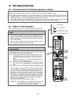
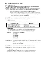
1HR.
TIMER
button

ON/OFF
operation
button

ACL
(Reset)
button

QUIET
button

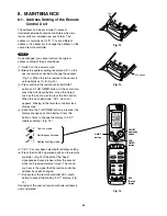
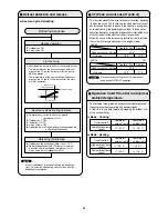
Test run mode

Self-diagnostic mode

Address setting mode

Fig. 13

Fig. 14

Fig. 15

Tab

ACL button

8.  MAINTENANCE

8-1.  Address Setting of the Remote 

Control Unit

The address can be set in order to prevent 

interference between remote controllers when two 

indoor units are installed near each other. The 

address is normally set to "A." To set a different 

address, it is necessary to change the address on the 

second remote controller.

Once changed, you cannot restore the original 

address setting of the air conditioner.

(1) Switch  on the power source.

(2) Break the address-setting tab marked "A" on the 

second remote controller to change the address 

(Fig. 13). When the tab is removed, the adress is 

automatically set to B (Fig. 14).

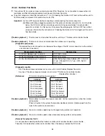
(3) Press and hold the remote controller QUIET 

button and 1 HR TIMER button. At the same time, 

press the ACL(reset) button. Use a thin object 

such as the tip of a pen to press the ACL button. 

When this has been done, "oP-1" (test run) 

appears, blinking, in the remote controller clock 

display area.

(4) Each time the 1 HR TIMER button is pressed, the 

display changes as shown below. Press this 

button 2 times to change the display to "oP-7" 

(address setting). (Fig. 15) 

(5) "oP-7" has now been selected for address setting.

(6) Press the ON/OFF operation button on the remote 

controller. (Fig. 15) Check that the "beep" 

signalreceived sound is heard from the second 

indoor unit (approximately 5 times). The sound 

you hear is the signal that the remote controller 

address has been changed.

(7) Finally press the remote controller ACL (reset) 

button to cancel the blinking "oP-7" display. (Fig. 

15)

Changing of the second remote controller address is 

now completed.

NOTE

30

Summary of Contents for AEI55AH

Page 1: ...Model No Product Code No AEI55AH 3 870 310 70 1 852 336 57 AEI70AH 3 870 310 71 1 852 336 58 TECHNICAL SERVICE MANUAL AIR CONDITIONER AWI55AHL AWI70AHL AEI55AH AEI70AH IMPORTANT These air conditioners employ new refrigerant R410A Pay special attention when servicing the unit Indoor Unit Outdoor Unit DC INVERTER SPLIT SYSTEM AIR CONDITIONER Destination Europe FILE NO ...

Page 2: ...e fire hazard When Transporting Be careful when picking up and moving the indoor and outdoor units Get a partner to help and bend your knees when lifting to reduce strain on your back Sharp edges or thin aluminum fins on the air conditioner can cut your fingers When Installing In a Ceiling or Wall Make sure the ceiling wall is strong enough to hold the unit s weight It may be necessary to construc...

Page 3: ...aracteristics 6 2 Electric Wiring Diagrams 7 INSTALLATION INSTRUCTIONS 7 1 Installation Site Selection 7 2 Recommended Wire Length and Diameter 7 3 Remote Control Unit Installation Position 7 4 How to Test Run the Air Conditioner 7 5 Remove the Grille to Install the Indoor Unit 8 MAINTENANCE 8 1 Address Setting of the Remote Control Unit 8 2 Disconnecting and Connecting Positive Connector for Outd...

Page 4: ...t of Insulation Resistance 11 2 Checking Continuity of Fuse on PCB Ass y 12 REFRIGERANT R410A SPECIAL PRECAUTIONS WHEN SERVICING UNIT 12 1 Characteristics of New Refrigerant R410A 12 2 Checklist before Servicing 12 3 Tools Specifically for R410A 12 4 Tubing Installation Procedures 12 5 In Case of Compressor Malfunction 12 6 In Case Refrigerant is Leaking 12 7 Charging Additional Refrigerant 12 8 R...

Page 5: ...GE Maximum Minimum Maximum Minimum 32 C D B 23 C W B 19 C D B 14 C W B 27 C D B 16 C D B 43 C D B 15 C D B 24 C D B 18 C W B _ D B 15 C W B Temperature Indoor Air Intake Temp Outdoor Air Intake Temp Cooling Heating 5 ...

Page 6: ...nnections Unit Dimensions Height Operation Sound Electrical Rating Air Circulation High Moisture Removal High W Power Input V A Available Voltage Range Running Amperes Refrigerant Tube Kit Accessories Narrow tube Wide tube Refrigerant mm in Tube Diameter mm in 0 285 48 0 379 12 0 380 44 0 15 0 0 125 740 1 012 1 065 218 880 285 289 1 140 Outdoor Unit Indoor Unit 298 670 6 35 1 4 12 7 1 2 m Max allo...

Page 7: ...ensions Height Operation Sound Electrical Rating Air Circulation High Moisture Removal High W Power Input V A Available Voltage Range Running Amperes Refrigerant Tube Kit Accessories Narrow tube Wide tube Refrigerant mm in Tube Diameter mm in 0 367 63 0 379 12 0 413 59 0 15 0 0 125 860 1 032 1 065 218 900 320 289 1 140 Outdoor Unit Indoor Unit 298 740 6 35 1 4 15 88 5 8 m Max allowable tubing leng...

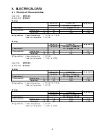
Page 8: ...V 3 15A Control Circuit Fuse Controls 1 D94 L845 RCS 3HVPSN4E Fan Cross Flow Control PCB CB AWI55AHL Part No Fan Motor Remote Control Unit Coil Resistance Ohm Ambient Temp 25 o C Each Pair of Terminal 400 7 Safety Device Rating Type Model Over Current Protection 8 Ambient Temp 20 o C Nominal Output W Coil Resistance Ohm Flap Motor Type Stepping Motor Rough Measure RPM Cool Heat Run Capacitor Type ...

Page 9: ... 8 Ambient Temp 20 o C Nominal Output W Coil Resistance Ohm Safety Device Rating Type Model Over Current Protection Coil Resistance Ohm Ambient Temp 25 o C Each Pair of Terminal 400 7 Control PCB CB AWI70AHL Part No Fan Motor Remote Control Unit DC 12V Heat Exchanger Coil Microprocessor 250V 3 15A Control Circuit Fuse Controls 1 D94 L845 RCS 3HVPSN4E Fan Cross Flow Coil Rows Fin Pitch mm 1 3 Face ...

Page 10: ... 0 482 S T 0 482 T R 0 482 Yes Yes Safety Device Yes Run Capacitor CS 7L115 Open 115 o C Close 95 o C Yes Internal Controller Aluminum Plate Fin Copper Tube 2 1 2 Face Area m2 0 510 Coil Rows Fin Pitch mm Heat Exchanger Coil Microprocessor 250V 25A Control Circuit Fuse Controls 1 D420 Fan Propeller Ambient Temp 20 o C DAJ12 55J71A CR 1 Control PCB CB CRV184EH Part No Fan Motor Type Compressor Mode...

Page 11: ...0 36 V W 0 36 W U 0 36 Open 115 o C Close 95 o C Yes Internal Controller Aluminum Plate Fin Copper Tube 2 1 4 Face Area m2 0 595 Coil Rows Fin Pitch mm Heat Exchanger Coil Microprocessor 250V 25A Control Circuit Fuse Controls 1 D460 Fan Propeller Ambient Temp 20 o C SIC 71FW D490 1 1 Control PCB CB CRV244EH Part No Fan Motor Type Compressor Model Nominal Output Compressor Oil Amount Coil Resistanc...

Page 12: ...10 15 20 25 30 35 40 Indoor air temp sensor Model PTM D51H S3 2 TH2 Indoor heat exchanger sensor Model PTM D51H S3 2 TH1 Compressor temp sensor Model TKS293B Resistance k ohm Resistance k ohm Temperature C Temperature C Outdoor air temp sensor Model TKS295B Outdoor heat exchanger sensor Model TKS292B 40 35 30 25 20 15 10 5 0 20 15 10 5 0 5 10 15 20 Temperature C Resistance k ohm 12 ...

Page 13: ...3 DIMENSIONAL DATA Indoor Unit AWI55AHL AWI70AHL Unit mm 13 ...

Page 14: ...80 136 12 36 334 310 285 I D 1 8 2 I D 2 3 6 670 18 55 111 166 2 145 AIR DISCHARGE AIR INTAKE AIR INTAKE Narrow tube service valve dia 6 35 1 4 Wide tube service valve dia 12 70 1 2 Outdoor Unit AEI55AH Unit mm 14 ...

Page 15: ...0 85 136 12 35 369 345 320 I D 1 8 5 I D 2 3 6 740 18 38 113 114 51 AIR DISCHARGE AIR INTAKE AIR INTAKE Narrow tube service valve dia 6 35 1 4 Wide tube service valve dia 15 88 5 8 Outdoor Unit AEI70AH Unit mm 15 ...

Page 16: ...door Unit AWI55AHL AWI70AHL Outdoor Unit AEI55AH AEI70AH Insulation of Refrigerant Tubing Because capillary tubing is used in the outdoor unit both the wide and narrow tubes of this air conditioner become cold To prevent heat loss and wet floors due to dripping of condensation both tubes must be well insulated with a proper insulation material The thickness of the insulation should be a min 8 mm A...

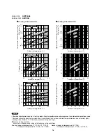
Page 17: ...of rating condition Black dots in above charts indicate the following rating conditions NOTE Cooling Heating 25 30 35 40 5 0 5 10 15 20 25 Outdoor air temperature C Outdoor air temperature C 20 C 17 C Indoor air temp 23 C Outdoor air temperature C Outdoor air temperature C 25 9 8 7 6 30 35 40 5 0 5 11 10 9 8 7 6 5 10 15 20 25 Operating current A 17 C Indoor air temp 23 C 20 C 25 10 12 14 16 18 20 ...

Page 18: ...current A Indoor discharge air temperature C Indoor discharge air temperature C 25 30 35 40 5 0 5 10 15 20 25 Outdoor air temperature C Outdoor air temperature C 20 C 17 C Indoor air temp 23 C Outdoor air temperature C Outdoor air temperature C 25 15 14 13 12 11 10 9 30 35 40 5 0 5 16 15 14 13 12 11 10 10 15 20 25 Operating current A 17 C Indoor air temp 23 C 25 10 12 14 16 18 20 30 35 40 5 0 5 10...

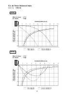
Page 19: ...air velocity m s Vertical distance m Room air temp 27 C Fan speed High Cooling Flap angle 0 Axis air velocity 0 Flap angle 30 Axis air velocity 30 Flap angle 45 Axis air velocity 45 Flap angle 60 Axis air velocity 60 5 2 Air Throw Distance Charts Indoor Unit AWI55AHL 0 1 2 3 4 0 1 2 3 4 5 6 7 8 9 10 0 1 2 3 4 5 0 1 2 3 4 5 6 7 8 9 19 ...

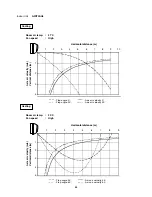
Page 20: ...istance m Axis air velocity m s Vertical distance m Room air temp 27 C Fan speed High Cooling Flap angle 0 Axis air velocity 0 Flap angle 30 Axis air velocity 30 Flap angle 45 Axis air velocity 45 Flap angle 60 Axis air velocity 60 Indoor Unit AWI70AHL 0 1 2 3 4 0 1 2 3 4 5 6 7 8 9 10 0 1 2 3 4 5 0 1 2 3 4 5 6 7 8 9 20 ...

Page 21: ...Unit Outdoor Unit Complete Unit Fan Motor Performance at Rating conditions Running amp A 0 3 Power input W 34 7 4 1 575 Indoor Unit AWI70AHL Outdoor Unit AEI70AH Indoor Unit Outdoor Unit Complete Unit Fan Motor Fan Motor Compressor Performance at 230V Single phase 50Hz Rating conditions Running amp A 0 51 Power input W 55 10 19 2 300 Fan Motor Compressor 230V Single phase 50Hz 10 76 2 432 Rating c...

Page 22: ...COIL THERMISTOR COMPRESSOR THERMISTOR COMPRESSOR MOTOR RED WHT BLU RED WHT BLU FERRITE CORE FERRITE CORE 3P CONNECTOR OVERLOAD RELAY OLR WHT WHT Indoor Unit AWI55AHL 8FA2 5257 82800 0 EVAPORATOR TERMINAL BASE WHT BLK RED 1 2 3 4 GRN YEL LAMP 10P WHT FLAP 5P WHT FLAP CONNECTOR FLAP MOTOR RED PNK BLU BRN YEL 1 2 3 4 5 1 2 3 4 5 1 2 3 4 5 1 2 3 4 5 AC1 AC2 SI WHT RED WHT WHT WHT WHT WHT WHT WHT WHT 1...

Page 23: ...or Unit AEI70AH 8FA2 5257 59800 4 1 2 1 2 1 2 1 2 1 2 1 2 3 2 1 1 2 3 CM GRN YEL RV MV FM 4WAY VALVE COIL FAN MOTOR MAGNETIC COIL N L TERMINAL BASE GND 1 2 3 4 L N 1 2 1 2 3 4 1 2 3 4 5 5 1 2 3 4 1 2 3 4 5 6 7 5 6 7 1 2 3 4 5 6 7 1 2 1 2 1 2 3 4 1 2 3 4 1 2 3 4 1 2 3 4 REACTANCE WHT WHT 2P CONNECTOR RED 2P CONNECTOR BLK 2P CONNECTOR WHT WHT WHT BRN BRN L2 L1 OLR0 OLR1 W W HEATER1 HEATER0 HIC HIC H...

Page 24: ...side allow room for operation and maintenance as well as unrestricted air flow around the unit Fig 1 install the unit within the maximum elevation difference H above or below the outdoor unit and within a total tubing length L from the outdoor unit as detailed in Table 1 and Fig 2 Install the indoor unit more than 1 meter away from any antenna or power lines or connecting wires used for television...

Page 25: ... Unit Fig 4 AVOID heat sources exhaust fans etc Fig 4 damp humid or uneven locations DO position the outdoor unit in a protected location where snow will not blow into it choose a place as cool as possible choose a place that is well ventilated allow enough room around the unit for air intake exhaust and possible maintenance Fig 5a or 5b provide a solid base level concrete pad concrete block 10 40...

Page 26: ...size of wire and wiring method etc Each wire must be firmly connected No wire should be allowed to touch refrigerant tubing the compressor or any moving part Be sure to connect the power supply line to the outdoor unit as shown in the wiring diagram The indoor unit draws its power from the outdoor unit Do not run wiring for antenna signal or power lines of television radio stereo telephone securit...

Page 27: ...ol unit in the following places In direct sunlight Behind a curtain or other place where it is covered More than 8 m away from the air conditioner In the path of the air conditioner s airstream Where it may become extremely hot or cold Where it may be subject to electrical or magnetic interference Where there is an obstacle between the remote control unit and the air conditioner since a check sign...

Page 28: ... QUIET button 2 Start Cooling mode test run by pressing the ON OFF operation button of the remote controller Fig 8a This starts the fan producing uncooled forced air with the 3 indicator lamps OPERATION lamp TIMER lamp and QUIET lamp on the main unit blinking Fig 8c After 3 minutes the system shifts into cooling operation and cool air will start to be felt Cool mode test run is unaffected by the r...

Page 29: ...ame Fig 11a 6 Pull the grill toward you to remove it How to replace the grille 1 When installing the grille place the bottom of the grille into the frame first Fig 11b Then insert the tabs on the top of the grille and on the front face into the frame 2 Make sure that the grille and frame are firmly fitted together by engaging the tabs 3 Attach the thermistor on the grille Fig 10a 4 Close the cover...

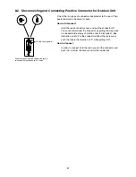
Page 30: ...utomatically set to B Fig 14 3 Press and hold the remote controller QUIET button and 1 HR TIMER button At the same time press the ACL reset button Use a thin object such as the tip of a pen to press the ACL button When this has been done oP 1 test run appears blinking in the remote controller clock display area 4 Each time the 1 HR TIMER button is pressed the display changes as shown below Press t...

Page 31: ...lways hold the cover to disconnect See illustration at left For the connector without the resin cover push the lock in the direction of 2 while pulling it off How to Connect In order to connect hold the resin cover of the connector and push it in Confirm the click sound for the inside lock Pull the cover upward When the cover is pulled upward the lock is released with the sequence of 1 and 2 8 2 D...

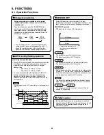
Page 32: ... below the detected room temperature in the case of cooling operation and 2 C above the room temperature in the case of heating operation The flap and fan speed settings are AUTO GREEN RED Lamp Off COOL HEAT STOP When AUTO mode is selected the microprocessor calculates the difference between the set temperature and the room temperature and automatically switches to Cooling or Heating mode As shown...

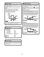
Page 33: ...ficing comfort This function is convenient when gentle heating is needed HIGH POWER NIGHT SETBACK Lamp colors Timer backup This function acts to raise the power but keeps the AC system in the same operating mode This function is set with the HIGH POWER button on the remote controller It can be set regardless of the temperature and fan speed settings HIGH POWER operation from remote controller The ...

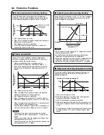
Page 34: ...onditioner will work less than the maximum frequency until it is turned off The Freeze Prevention Control during the Low Ambient Cooling Mode outside air temperature 15 C or lower is as follows The compressor stops when the temperature of indoor heat exchanger becomes less than 2 C The compressor restarts when the temperature of indoor heat exchanger becomes 8 C or higher Approx 53 At stability of...

Page 35: ...Mode Heating Cut off action High ambient temp cut off Thermo off t ambient temp Thermo on t ambient temp t 24 C t 20 C Low ambient temp cut off t 16 C Cooling Dry Heating Peak current cut off trips 22 5 Hz down 14 0 17 5 A AWI70 Heating operation Frost sensing Reverse cycle defrosting operation Defrosting Sequence Releasing of defrosting Outdoor fan ON 4 way valve ON Outdoor heating exchanger temp...

Page 36: ...ay Step 1 Press and hold the remote controller QUIET button and 1 HR TIMER button At the same time press the ACL reset button Use a pointed object such as the tip of a pen to press the ACL button When this has been done oP 1 test run appears blinking in the remote controller clock display area Step 2 Next press the 1 HR TIMER button once to change the display from oP 1 to oP 3 self diagnostics The...

Page 37: ...cuit board failure 1 Sensor open circuit or short circuit 2 Contact failure at connector or open circuit at terminal crimping location 3 Outdoor circuit board failure Outdoor circuit board failure 1 Mis wiring 2 AC power failure 3 Blown fuse 4 Power relay failure 5 Indoor or outdoor circuit board failure 1 HIC or power Tr failure 2 Outdoor fan does not turn 3 Instantaneous power outage 4 Service v...

Page 38: ...ers once every 8 seconds Control No Check items unit operation Apply the rated voltage between outdoor unit terminals L and N If there are no problems with the above then check the indoor unit Turn the power OFF before performing short circuiting procedures Refer to the previous pages when performing system self diagnostics So that the check can be made quickly indicators blink at first communicat...

Page 39: ...ellow Pin 6 PG blue Trouble symptom 3 Motor rotates for some time several seconds but then quickly stops when the indoor unit operates There is trouble in the system that provides feedback of motor rotation speed from the motor to the indoor unit controller Trouble symptom 4 Fan motor rotation speed does not change during indoor unit operation Trouble symptom 5 Fan motor rotation speed varies exce...

Page 40: ...ontroller Trouble symptom 4 Fan motor rotation speed does not change during outdoor unit operation Trouble symptom 5 Fan motor rotation speed varies excessively during outdoor unit operation Remedy for symptom 3 to 5 It is not possible to identify whether the trouble is outdoor unit controller trouble or motor trouble Therefore first replace the outdoor unit controller then if necessary replace th...

Page 41: ...distance from the noise source 1 Use shielded wires 2 Move unit away from the noise source Trouble Either of the following trouble may occur 1 The unit may stop suddenly during operation 2 Indicator lamps may flicker 2 Electromagnetic interference This refers to noise generated by high speed switching of the microcomputer and compressor This noise radiates through space and returns to the electric...

Page 42: ...g 1 11 1 2 Indoor Unit Clamp an aluminum plate fin or copper tube with the lead clip of the insulation resistance tester and measure the resistance by placing a probe on each terminal screw on the terminal plate Fig 2 Note that the ground line terminal should be skipped for the check 11 1 3 Outdoor Unit Clamp a metallic part of the unit with the lead clip of the insulation resistance tester and me...

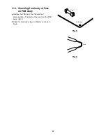
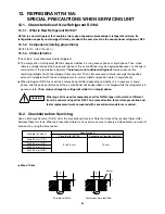
Page 43: ... Fig 6 Fuse 11 2 Checking Continuity of Fuse on PCB Ass y Remove the PCB Ass y from the electrical component box Then pull out the fuse from the PCB Ass y Fig 5 Check for continuity using a multimeter as shown in Fig 6 43 ...

Page 44: ...arge the specified amount of refrigerant with the new refrigerant at its normal mixed composition state in liquid phase When refrigerant R410A is used the composition will differ depending on whether it is in gaseous or liquid phase and the basic performance of the air conditioner will be degraded if it is charged while the refrigerant is in gaseous state Thus always charge the refrigerant while i...

Page 45: ...R22 and R407C No addition of compressor oil for R410A No additional charge of compressor oil is permitted No use of refrigerant other than R410A Never use a refrigerant other than R410A If refrigerant R410A is exposed to fire Through welding etc toxic gas may be released when R410A refrigerant is exposed to fire Therefore be sure to provide ample ventilation during installation work Caution in cas...

Page 46: ...can be com monly used for R22 R407C and R410A CAUTION The above tools specifically for R410A must not be used for R22 and R407C Doing so will cause malfunction of the unit For the above vacuum pump 1 2 and vacuum pump adapter 3 those for R22 type units can be used for R410A type However they must be used exclusively for R410A and never alternately with R22 and R407C For details on tubing installat...

Page 47: ...eplace it quickly 3 Checking for sealing Use nitrogen gas for the pressurized gas and never use a refrigerant other than R410A Also do not use oxygen or any flammable gas 4 Evacuation Use a solenoid valve installed vacuum pump so that even if power is cut off in the middle of evacuation of air due to a power interruption the valve will prevent the pump oil from flowing back The equipment may be da...

Page 48: ...frigerant cylinder use an electronic scale for charging refrigerant In this case if the volume of refrigerant in the cylinder becomes less than 20 of the fully charged amount the composition of the refrigerant starts to change Thus do not use the refrigerant if the amount in the charging cylinder is less than 20 Also charge the minimum necessary amount to the charging cylinder before using it to c...

Page 49: ...ing flux and wax for R410A Prevent oxide film from forming inside the tubes utilizing substitution with nitrogen N2 in the refrigerant circuit of the unit Leave ends of tubes open during welding 4 Checking for sealing Use nitrogen gas for the pressurized gas and never use a refrigerant other than R410A Also do not use oxygen or any flammable gas 5 Evacuation Use a solenoid valve installed vacuum p...

Page 50: ... R410A for existing units which use R22 This will cause the air conditioner to operate improperly and may result in a hazardous condition 12 8 2 Use of Existing Tubing If replacing an older unit that used refrigerant R22 with a R410A unit do not use its existing tubing Instead completely new tubing must be used CAUTION Never charge additional refrigerant if refrigerant is leaking from the unit Fol...

Page 51: ...ce button CANCEL button SENSOR button CLOCK button Advance button NIGHT SETBACK button HIGH POWER button OFF TIME setting buttons Return button QUIET button ADDRESS switch Temperature display selector button Time display selector button Display Sensor Transmitter ON OFF operation button ACL button MODE Selector button 1 HR TIMER button Cover closed INDOOR UNIT OPERATION lamp TIMER lamp QUIET lamp ...

Page 52: ...Via Varese 90 21013 Gallarate VA Italy Tel 39 0331 755111 Fax 39 0331 776240 http www argoclima com ...

Reviews: