background image

Subject to change · UMPCL 045_41733800 · 0321 · EN

Page 25

www.argo-hytos.com

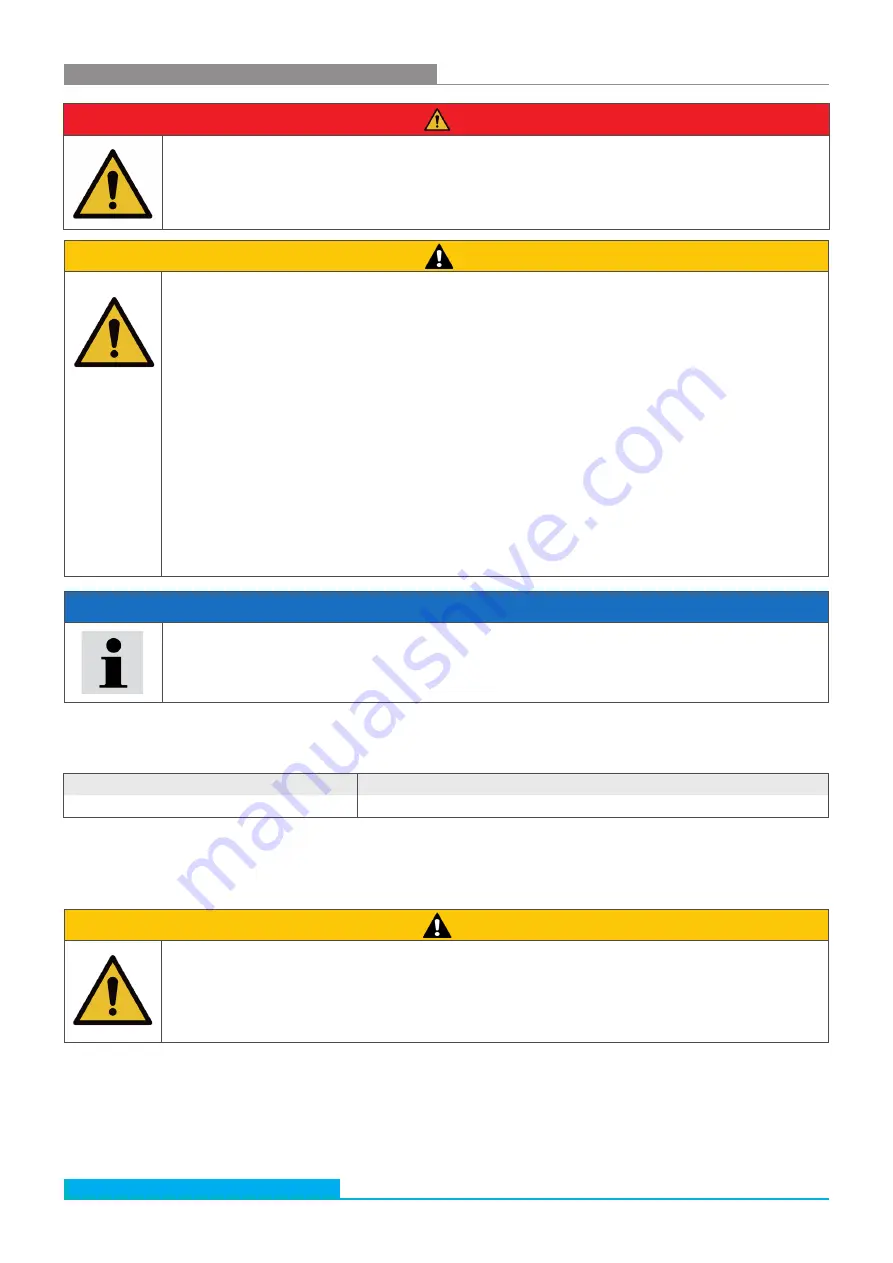
                      CAUTION

Hydraulic oil spills
Environmental hazard / risk of slipping


Before maintenance and repair work, completely drain the unit.


 In case of spills, cover the oil-covered surface immediately with an oil-binding medium.


 Then immediately dispose of the oil-binding medium according to the national environmental regulations.

Ignition hazard
Risk of electrostatic charge by poorly conducting hydraulic fluid.


  If the electrical conductivity of the hydraulic fluid is not known, please contact the manufacturer of the 
hydraulic fluid.

Risk of burns
Contact temperatures according to DIN EN563 (3) and DIN EN13202 (4) may be exceeded during 
operation.


Allow the filter to cool down before touching it.


11. Repair and maintenance

                    DANGER

Danger to life
Risk of electric shock


During repair work, turn off the unit and pull the mains plug.

               NOTE

Impaired function by dirt ingress into the pump.
The function of the filter unit is no longer guaranteed.


 During repair work, all parts coming in contact with the hydraulic medium, must be kept free of dirt and chips.

11.1     Maintenance overview

Except from the filter element, suction strainer, and OPCom screen protective elements the filter unit is maintenance-free.

Maintenance work

Maintenance interval

Checking / changing the filter element 

Once the clogging indicator responds at a permissible viscosity.

11.2  

Changing the filter element

1.  Pump the filter element empty (see Chapter 10.2 "Filtering of liquids in the bypass flow", point 7).
2.  Disconnect the off-line filter unit from the power supply and, if necessary, pull the mains plug.

                      CAUTION

Risk of burns
Contact temperatures according to DIN EN563 (3) and DIN EN13202 (4) may be exceeded during 
operation.


Allow the filter unit to cool down before touching it.


Table 7: Maintenance overview

Summary of Contents for UMPCL 045 Lightline

Page 1: ...does not release the user from his her own assessments and inspection Our products are subject to a natural wear and aging process All rights are reserved by ARGO HYTOS even in the event of industrial...

Page 2: ...ions 7 3 General instructions 8 4 Scope of delivery 9 5 About this product 10 5 1 Component overview 10 5 2 Operating elements 13 5 3 Identification of the product 14 6 Transport and storage 15 6 1 Tr...

Page 3: ...ing the suction filter element pump protection filter 27 11 4 1 Removing the suction filter 27 11 4 2 Installing the suction filter 27 11 5 Checking cleaning OPCom protective filters 28 12 Decommissio...

Page 4: ...h your product we use standardized safety instructions symbols terms and abbreviations For better understanding these are explained in the following sections 1 3 1 Safety instructions In this document...

Page 5: ...eaning If this information is not observed the product cannot optimally be used or operated Singular independent action step instruction 1 2 3 Numbered instruction The numbers indicate that the action...

Page 6: ...use described is improper and inadmissible If unsuitable products are installed or used in safety related applications unintended operating states may occur in the application which may cause personal...

Page 7: ...sonal injury and or material damage Therefore only use the product in safety relevant applications if this use is explicitly specified and permitted in the product documentation You may only put the p...

Page 8: ...premature wear or malfunction Make sure that connections hydraulic lines and attachment parts e g gauges are free from dirt and chips Prior to commissioning check that all hydraulic and mechanical co...

Page 9: ...Subject to change UMPCL 045_41733800 0321 EN Page 9 www argo hytos com 4 Scope of delivery This package includes 1 Filter and Recirculating Pump Unit UMPCL 045 1 Operating manual...

Page 10: ...r OPCom allows a particle measurement according to the latest standard Thus the level of contamination as well as the trend of the cleanliness of fluids can be observed Hose holder On both sides of th...

Page 11: ...ilters The filter unit is provided with screen filters These elements protect the OPCom partilce sensor from dirt which can block the oil flow Screen filters should be cleaned regularly Suction strain...

Page 12: ...dicator This switch monitors the pressure of the medium before and after the filter When the preset differential pressure is reached the optical indicator changes from green to red If the pressure dif...

Page 13: ...supplementary documentation OPCom Particle Monitor Safety and operating instructions Connection RS232 In the front panel of the UMPC 045 unit there is a serial interface via which the OPCom Particle M...

Page 14: ...321 EN Page 14 www argo hytos com 5 3 Identification of the product Serial number Type Manufacturing date encrypted Filter element type Fineness of the filter Nominal volume flow Maximum operating pre...

Page 15: ...tect it from humidity and condensation Fig 7 Transport rack The unit is mounted on a transport rack with two wheels This hand truck enables the unit to be transported without difficulty weight 88 kg e...

Page 16: ...pe plate of the motor the power source has appropriately been secured 16 A the cross section is of sufficient size cable and connection to the power source are in perfect condition The following steps...

Page 17: ...o prevent unintentional starting of the unit always switch off and unplug the unit 8 3 Venting To bleed the unit automatically loosen the black cap 3 on the ventilating valve 1 NOTE Do NOT unscrew the...

Page 18: ...ont panel of the UMPCL 045 unit there is a serial interface fig 5 page 13 via which the OPCom Particle Monitor can be read out and configured For this purpose a PC and an appropriate terminal program...

Page 19: ...5 l min The filter unit has a suction protection strainer on the suction side which must be serviced regularly A missing protective strainer can lead to the destruction of the pump Order No see spare...

Page 20: ...esired fill level 8 After completion of the operation pull the suction lance suction tube out of the container barrel and suck air for max 30 seconds Thus the residual oil from the filter housing and...

Page 21: ...the filter unit at the circuit breaker 10 Fix the suction lance suction pipe and the discharge pipe to the corresponding brackets at the filter unit NOTE Achieving the maximum cleaning performance In...

Page 22: ...mmersion depth of the suction lance in the hydraulic fluid NOTE At the beginning of the filtration filling of the filter unit may take several seconds Pumping Filtering 7 Monitor the process 8 After t...

Page 23: ...ertion depth of the suction pipe in the oil tank 8 Monitor the filling level at the machine or system and switch off the filter unit at the circuit breaker after having reached the desired fill level...

Page 24: ...le Counting Cleaning BEFORE filter Fig 16 Three way valve 6 Switch on the filter unit at the on off switch circuit breaker and let it operate for approx 5 min Initialization of the particle counter an...

Page 25: ...electric shock During repair work turn off the unit and pull the mains plug NOTE Impaired function by dirt ingress into the pump The function of the filter unit is no longer guaranteed During repair...

Page 26: ...the cover 1 Push the filter element at the cover in arrow direction 1 and remove it in arrow direction 2 2 Dispose of the filter element according to the national environmental legislation Waste code...

Page 27: ...ilter element pump protection filter 11 4 1 Removing the suction filter Fig 21 Removing the suction filter 1 2 3 4 11 4 2 Installing the suction filter 1 Always replace the sealing ring 3 after each c...

Page 28: ...Com protective filters 1 Provide a drip tray for residual oil and the contaminated filter element 2 Unscrew both filters 1 2 3 Clean filters using cleaning agent and compressed air If necessary instal...

Page 29: ...045_41733800 0321 EN Page 29 www argo hytos com 12 Decommissioning The filter unit UMPCL 045 is a component which does not have to be taken out of service Therefore the chapter in this manual does not...

Page 30: ...Subject to change UMPCL 045_41733800 0321 EN Page 30 www argo hytos com 13 Disassembly This chapter does not contain any information for your device...

Page 31: ...s disposal of the filter unit UMPCL 045 and the pressurized fluid can lead to environmental pollution Therefore dispose of the filter unit and the pressure fluid according to the national regulations...

Page 32: ...warranty of ARGO HYTOS applies to the delivered configuration and extensions which were taken into account during configuration The warranty expires after a conversion or extension that goes beyond th...

Page 33: ...stem in which the particle monitor OPCom Portable is installed Have the operating conditions or the area of application of the particle monitor OPCom Portable been changed Have modifications e g conve...

Page 34: ...filter element is reached Leakage at the suction hose falsification of the measurement results by free air in the oil air bubbles Rotary valve on lever position Pumping Replace filter element Check t...

Page 35: ...Subject to change UMPCL 045_41733800 0321 EN Page 35 www argo hytos com Fig 23 Dimension drawing 17 Technical specifications 17 1 Dimension drawing...

Page 36: ...042 01 p 2 0 0 3 bar Suction side Connection G 1 with hose DN 32 and suction lance when replacing the suction hose only use a spiral hose Pressure side Connection G1 with hose DN 25 and pressure lance...

Page 37: ...determination of the cleanliness class is possible in a viscosity range of 15 mm2 s to 300 mm2 s Electric drive 3 400 V 50 60 Hz UMPCL 045A adjustable nominal flow mm2 s viscosity range for 20 l min m...

Page 38: ...ilter unit UMPCL 045 to which this declaration pertains are in conformity with the following directives Directive 2006 42 EC Machinery Directive Directive 2014 30 UE EMC Directive Conformity with the...

Page 39: ...5 Filter element 2 Cover complete 3 O ring 1 Equipment rack 6 Hose 7 Fixture 8 Flat head screw 9 Motor 10 Pump not shown 11 Wheel 12 Cap 23 Hose clamp 17 Screen filter 16 Valve complete 19 Screw plug...

Page 40: ...Subject to change UMPCL 045_41733800 0321 EN Page 40 www argo hytos com Fig 27 Spare parts drawing 3 27 Ball valve 26 OPCom particle monitor 28 Power supply complete not shown 29 Pressure relief valve...

Page 41: ...1 13 Pressure hose 1 UM 045 0750 o Z DN 25 2 5 meters 14 Pipe 1 UM 045 0756 0 4 meter 15 Hose clamp 2 13797700 GBS 32 35mm W1 16 Valve complete 1 41247400 17 Screen filter 2 15077600 18 Pump block 1 F...

Page 42: ...e ARGO HYTOS SARL info fr argo hytos com Germany ARGO HYTOS GMBH info de argo hytos com Great Britain ARGO HYTOS Ltd info uk argo hytos com Hong Kong ARGO HYTOS Hong Kong Ltd info hk argo hytos com In...

Reviews: