Arecont Vision MegaBall AV3146DN-3310-D-LG Installation Manual Download Page 10

Arecont Vision MegaBall™ Installation Manual 

9 | P a g e


NOTE 1: Basic Mode: software will automatically 
discover and change / assign IP address to match 
PC subnet if they are not locked.  

NOTE 2: Advanced Mode: software will 
automatically discover but allow manual update of 
the IP address. See “AV100 Installation Manual” 
(found on the CD) for details on Advanced Mode. 

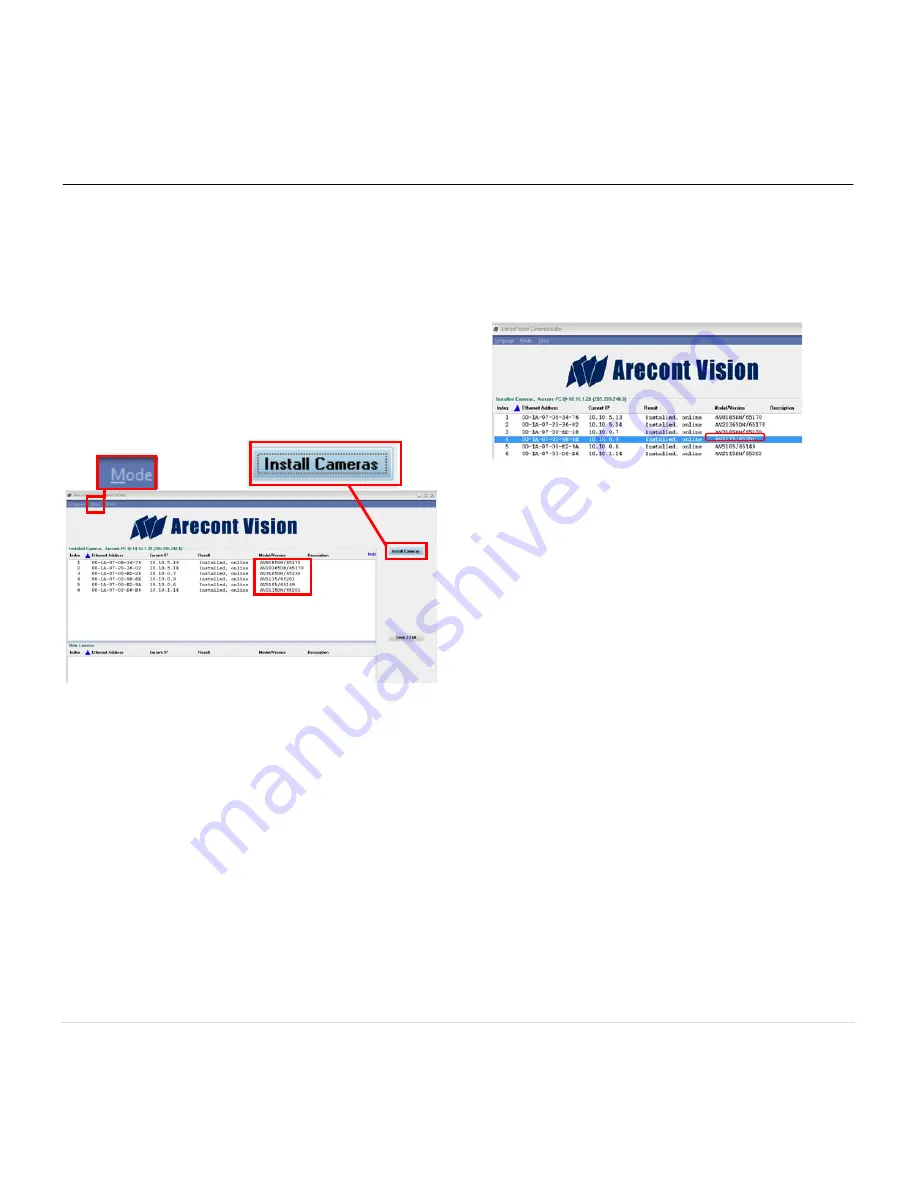
NOTE3: User can verify camera model number and 
FW version of all cameras as shown in Image 23


Image 22


29.  For basic mode, select “Install Cameras” on 

the Arecont Vision Camera Installer as shown 
in 

Image 22

 
30.  Confirm that all the cameras connected to the 

network switch appear in the upper window. 

 
31.  Repeat 

Step 29 

if all of the cameras do not 

appear in the upper window. 

CAUTION: If the software does not find a camera, 
the software utility may be blocked by the anti-virus 
or Windows

®

NOTE : Double click the camera model on the 
Camera Installer as shown in Image 22 to access 
the camera web interface. See “AV Camera Web 
Page User Manual” (found on the CD) for details on 
the web interface.  

 firewall. Before turning them off, 

please consult your IT manager.  


Image 23


32.  When all cameras are discovered and display 

“Installed, online”, select “Save/Exit.” The 
AV100 application main menu will appear.  
 

33.  From the “AV100 Application Manager” menu, 

select “Run” next to “Live video” to view live 
images.   


NOTE: See the “AV100 Installation Manual” 
(found on CD) for details on camera 
configurations. 


Summary of Contents for MegaBall AV3146DN-3310-D-LG

Page 1: ...Arecont Vision MegaBall Installation Manual 0 P a g e...

Page 2: ...e mounting surface for camera installation 3 Plug the Ethernet cable into the MegaBall PoE female RJ45 connector Image 2 NOTE If the camera will be powered via PoE please skip to step 5 Image 2 4 If t...

Page 3: ...bracket ring may result in scratches on the bracket joint Incorrect installation practices are not covered under warranty 7 For the vari focal model adjust the focus iris and field of view using the p...

Page 4: ...head screwdriver Not included but needed Image 1 Mounting the Camera 1 Remove the camera and hardware from the box 2 Using the mounting template prepare the mounting surface for camera installation 3...

Page 5: ...ace for mounting In ceiling Mount Installation Optional 8 Insert the in ceiling mount camera into the hole 9 Tighten the lever screws until the flush mount is snug as shown in Image 5 The Support Arm...

Page 6: ...tion as shown in Image 7 Image 7 13 For the vari focal model adjust focus iris and field of view using the provided Security L Key Image 1H on Page 3 as shown in Image 8 Adjusting the Focus Iris and F...

Page 7: ...wn in Image 12 Retighten the set screws once focusing is complete 16 Remove the O ring Image 1D on Page 3 from the bezel by pushing on the 4 drift pins on the back of bezel shown in Image 13 Dome Cove...

Page 8: ...screws and rubber cable from default bezel as shown in Image 15 Image 15 22 Install screws and dome bubble on the audio bezel as shown in Image 16 Image 16 23 Secure the dome cover to the camera using...

Page 9: ...250 Ohm resistor and a debouncing circuit Duration of any input signal should be at least 5ms to comply with the requirements of the debouncing circuit Yellow Digital IN Red Digital IN Green Digital...

Page 10: ...network switch appear in the upper window 31 Repeat Step 29 if all of the cameras do not appear in the upper window CAUTION If the software does not find a camera the software utility may be blocked...

Page 11: ...ed but needed Image 24 1 Remove wall mount and hardware from the box 2 Using the mounting template prepare the mounting provisions for camera installation 3 Attach surface mount Image 1B on Page 3 to...

Page 12: ...needed Image 27 1 Remove pendant mount and hardware from the box 2 Using the mounting template prepare the mounting provisions for camera installation 3 Attach surface mount Image 1B on Page 3 to pen...

Page 13: ...apter and hardware from the box 2 Remove the conduit plug by first removing the socket set screw using the provided hex key C as shown on Image 31 3 Attach the junction box adapter to the wall using d...

Page 14: ...ge 33 2 Phillips head screwdriver Not included but needed Common electrical box such as single gang box double gang box or square electrical boxes shown in Image 34 1 4 1 Remove the electrical box ada...

Page 15: ...Arecont Vision MegaBall Installation Manual 1 P a g e R...

Reviews: