


Arecont Vision
Surround
Video
®
Omni Installation Manual
Page | 12 [email protected]
Surround
Video® Omni
Focusing Alternate Lenses
When focusing the 6mm, 8mm, 12mm or 16mm lens options you will encounter a focus shift when using the
bubble. To account for this follow these steps:
1.
Focus the camera without the bubble.
2.
Rotate the lens per the chart below. The rotation will account for most of the focus shift.
3.
Put cover with bubble on. You should be close to being focused.
4.
Remove cover and rotate a couple degrees at a time in either direction until you gain the desired image.
Example: Using a 16mm lens you will focus the lens without the bubble until you get the desired image. Rotate
the lens almost ¾ of a turn (250°). Put the bubble on and view the image. It should be almost in focus. Remove
the bubble and rotate a degree or two in one direction and view the image with the bubble on. Depending on
the image you may need to adjust in the opposite direction or continue in the same direction until the desired
image is obtained.
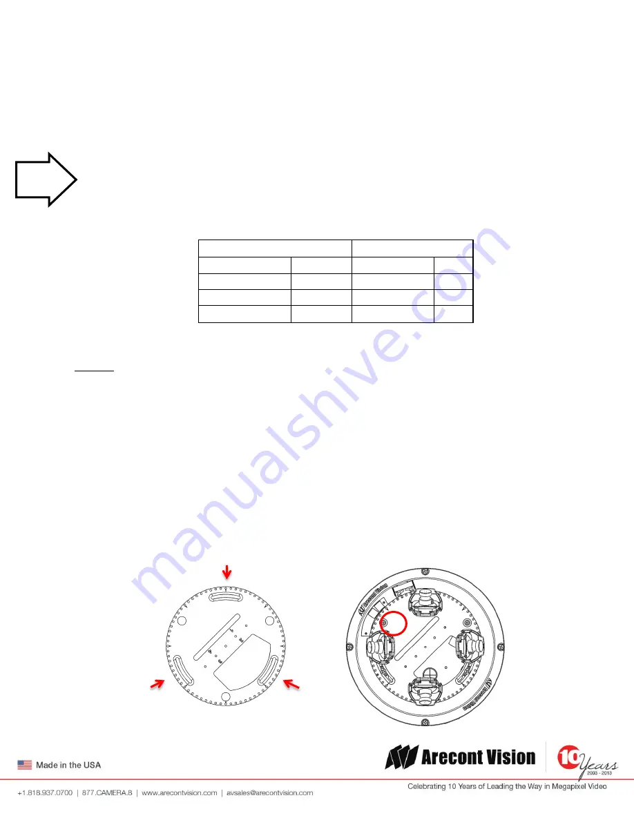
Accessing the Digital Input and Output Connector
The 4 position connector inside camera housing located on the main circuit board used for I/O can be accessed
by removing the track plate. Simply loosen the three screws indicated in the image below, lift the track plate
and find the connector. The approximate connector position is indicated by the red circle below.
Lens
Rotation
MPM16.0
16mm
<3/4 CCW
250°
MPM12.0
12mm
1/4 CCW
90°
MPM8.0
8mm
>1/8 CCW
60°
MPM6.0
6mm
1/8 CCW
45°
Tech
Tip