


28
MD1132
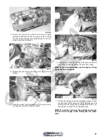
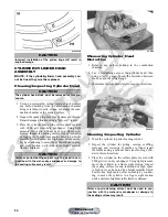
8. Remove the cam chain tensioner by lifting it from
the chain cavity; then remove the two lower nuts
securing the cylinder head to the cylinder, one in
front and one in rear.
MD1192
9. Remove the four cylinder head cap screws and wash-
ers. Note that the two cap screws on the right side of
the cylinder head nearest the cam sprocket are longer
than the two cap screws on the left (spark plug) side.
CD211
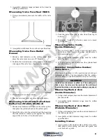
10. Remove the cylinder head from the cylinder, remove
the gasket, and account for two alignment pins.
MD1163
11. Remove the cam chain guide.
MD1173
C. Cylinder
D. Piston
NOTE: Steps 1-11 in the preceding sub-section
must precede this procedure.
12. Remove the two nuts securing the right side of the
cylinder to the right-side crankcase half.
KC337A
AT THIS POINT
To service valves and cylinder head, see Servicing Top-
Side Components sub-section.
AT THIS POINT
To inspect cam chain guide, see Servicing Top-Side
Components sub-section.
Manual
Table of Contents


