


5-6
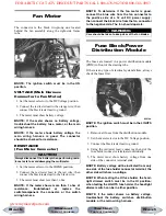
Speed Sensor
1. Set the meter selector to the DC Voltage position.
2. With appropriate needle adapters on the meter
leads, connect the red tester lead to the voltage
lead (V); then connect the black tester lead to the
ground lead (G).
KC248A
3. Turn the ignition switch to the ON position.
4. The meter must show greater than 5.0 volts.
5. Leave the black tester lead connected; then con-
nect the red tester lead to the signal lead pin (S).
6. Slowly move the ATV forward or backward; the
meter must show 0 and 6 volts alternately.
NOTE: If the sensor tests are within specifica-
tions, the speedometer must be replaced (see Sec-
tion 9).
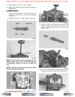
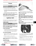
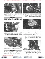
To replace a speed sensor, use the following proce-
dure.
1. Disconnect the three-wire connector from the
speed sensor; then remove the cap screw securing
the sensor to the sensor housing.
2. Remove the sensor from the sensor housing
accounting for an O-ring.
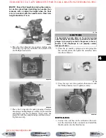
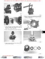
3. Install the new speed sensor into the housing with
new O-ring lightly coated with multi-purpose
grease; then secure the sensor with the cap screw
(threads coated with blue Loctite #242). Tighten
securely.
CD071
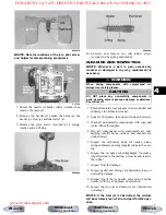
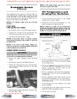
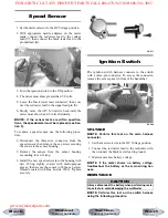
Ignition Switch
The ignition switch harness connects to the switch
with a three-pin connector. To access the connector,
remove the access panel in front of the handlebar.
KC209
VOLTAGE
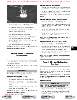
NOTE: Perform this test on the main harness
connector.
1. Set the meter selector to the DC Voltage position.
2. Connect the red meter lead to the red/white wire;
then connect the black meter lead to ground.
3. Meter must show battery voltage.
NOTE: If the meter shows no battery voltage,
troubleshoot the battery or the main wiring har-
ness.
RESISTANCE
NOTE: Perform this test on the switch harness
using the following procedure.
CAUTION
Always disconnect the battery when performing resis-
tance tests to avoid damaging the multimeter.
Next
Back
Section
Table of Contents
Manual
Table of Contents
FOR ARCTIC CAT ATV DISCOUNT PARTS CALL 606-678-9623 OR 606-561-4983
www.mymowerparts.com


