


The function outputs the START, TRIP and BLOCKED signals which can be used for direct I/O
controlling and user logic programming. The function generates general time-stamped ON/OFF events
to the common event buffer from each of the three (3) output signals. In the instant operating mode the
function outputs START and TRIP events simultaneously with an equivalent time stamp. The time stamp
resolution is 1 ms. The function also provides a cumulative counter for the START, TRIP and BLOCKED
events.
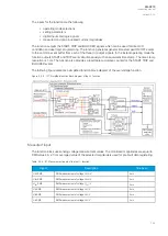
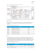
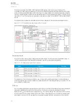
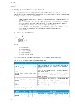
The following figure presents a simplified function block diagram of the neutral overvoltage function.
Figure. 5.3.10 - 113. Simplified function block diagram of the U0> function.
Measured input
The function block uses analog voltage measurement values. The function block uses RMS values. A
-20 ms averaged value of the selected magnitude is used for pre-fault data registering.
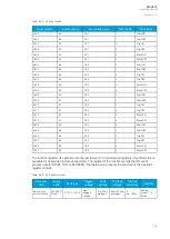
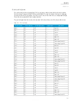
Table. 5.3.10 - 103. Measurement inputs of the U0> function.
Signal
Description
Time base
U0RMS
RMS measurement of voltage U0/V
5ms
U
L1
RMS
RMS measurement of voltage U
L1
/V
5ms
U
L2
RMS
RMS measurement of voltage U
L2
/V
5ms
U
L3
RMS
RMS measurement of voltage U
L3
/V
5ms
The selection of the AI channel currently in use is made with a setting parameter. In all possible input
channel variations the pre-fault condition is presented with a 20 ms averaged history value from -20 ms
from a START or TRIP event.
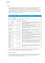
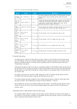
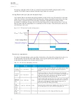
Pick-up
The
U
set
setting parameter controls the pick-up of the U0> function. This defines the maximum allowed
measured voltage before action from the function. The function constantly calculates the ratio
between the
U
set
and the measured magnitude (
U
m
) for neutral voltage. The reset ratio of 97 % is built
into the function and is always relative to the
U
set
value. The setting value is common for all measured
amplitudes, and when the
U
m
exceeds the
U
set
value it triggers the pick-up operation of the function.
A
AQ
Q-C213
-C213
Instruction manual
Version: 2.04
157