10
2580 series Hydraulic Installation Tools (HK961)
The operating efficiency of Huck equipment is directly
related to performance of the entire system, including tool,
nose assembly, hoses, trigger assembly, and Powerig®.
An effective preventive maintenance program includes
scheduled inspections of the system to detect and correct
minor troubles.
SYSTEM INSPECTION/PREVENTIVE MAINTENANCE
- Inspect tool and nose assembly daily for damage
and wear. Before each use, verify that the tool, hoses,
fittings, couplings, and trigger connections are secure,
undamaged, and free of leaks; replace as necessary. Clear
air-lines of dirt and water.
- Inspect tool, hoses, and Powerig during operation to
detect abnormal heating, leaks, or vibration.
- Service the tool in a clean, well-lighted area. Take
special care to prevent contamination of pneumatic and
hydraulic systems.
- Carefully handle all parts and components. Before
re-assembly, examine them for damage and wear;
replace when necessary. Replace O-rings and Back-up
rings whenever the tool is disassembled.
- Have available all necessary hand tools (standard and
special); a half-inch brass drift and wood block; an arbor
press; and a soft-jaw vise. Unsuitable hand tools could
damage tool. See
K
Its
& a
ccessorIes
.
- Follow the disassembly and assembly procedures in
this manual. If Huck-recommended procedures are not
followed, tool damage could result.
- Disassemble and assemble tool components in a straight
line. Do NOT bend, twist, or apply undue force. Always
apply continuous steady pressure to disassemble a
component. An arbor press provides steady pressure to
press a component into or out of an assembly.
- Never force a misaligned component. Reverse the
procedure, correct the misalignment, and start over.
FLUID MAINTENANCE
See
s
pecIfIcatIons
for fluid type. For fluid maintenance,
refer to NAS 1638 class 9, ISO CODE 18/15, or SAE level
6. Dispose of fluid in accordance with local environmental
regulations. Recycle steel, aluminum, and plastic parts in
accordance with local lawful and safe practices.
STANDARD SEALANTS, LUBRICANTS
- Apply Parker Threadmate
®
, Loctite
®
567, or Slic-Tite
®
to
male pipe threads per manufacturer’s instructions (to
ease
assembly and to prevent leaks)
.
- Smear
LUBRIPLATE
®
130-AA or
SUPER-O-LUBE
®
on
rings
and mating parts to ease assembly and to prevent
nicking/pinching rings on rough/tight spots.
POWERIG MAINTENANCE
Maintenance instructions and repair procedures are in the
appropriate Powerig Instruction Manual.
TOOL MAINTENANCE
Whenever disassembled, and at regular intervals,
depending on use, replace all O-rings and Back-up rings.
Tool-specific Spare Parts Service Kits should be kept
on hand. Inspect cylinder bore, piston, piston rod, and
unloading valve for scored surfaces, excessive wear, and
damage; replace as necessary
.
NOSE ASSEMBLY MAINTENANCE
Clean nose assemblies
in mineral spirits to clear jaws and
rinse metal chips and dirt. For a more thorough cleaning,
disassemble the nose assembly. Use a pointed “pick” to
remove embedded particles from the pull grooves of the
jaws. Clean
all parts of any assembly with UNITIZED
TM
Jaws
in mineral spirits or isopropyl alcohol only; do not let jaws
come in contact with other solvents. Do not let jaws soak;
dry them
immediately
after cleaning. Huck recommends
drying other parts before re-assembling.
Maintenance
CAUTIONS:
Consult the Material Safety Data Sheet
(MSDS) before servicing tool.
Keep foreign matter out of the hydraulic
system. Keep separated parts away from
dirty work surfaces.
Dirt and debris in hydraulic fluid causes valve
failures in tool and Powerig
®
.
Check the Assembly Drawings in this manual
for the proper direction of the flats on the
dump valve.
Do not use TEFLON
®
tape on pipe threads.
Tape can shred and break free into fluid
lines, resulting in malfunctions.
Damaged jaw teeth of a nose assembly, or
debris packed between teeth, will result
in failure of fastener installation, or faulty
fastener installation.
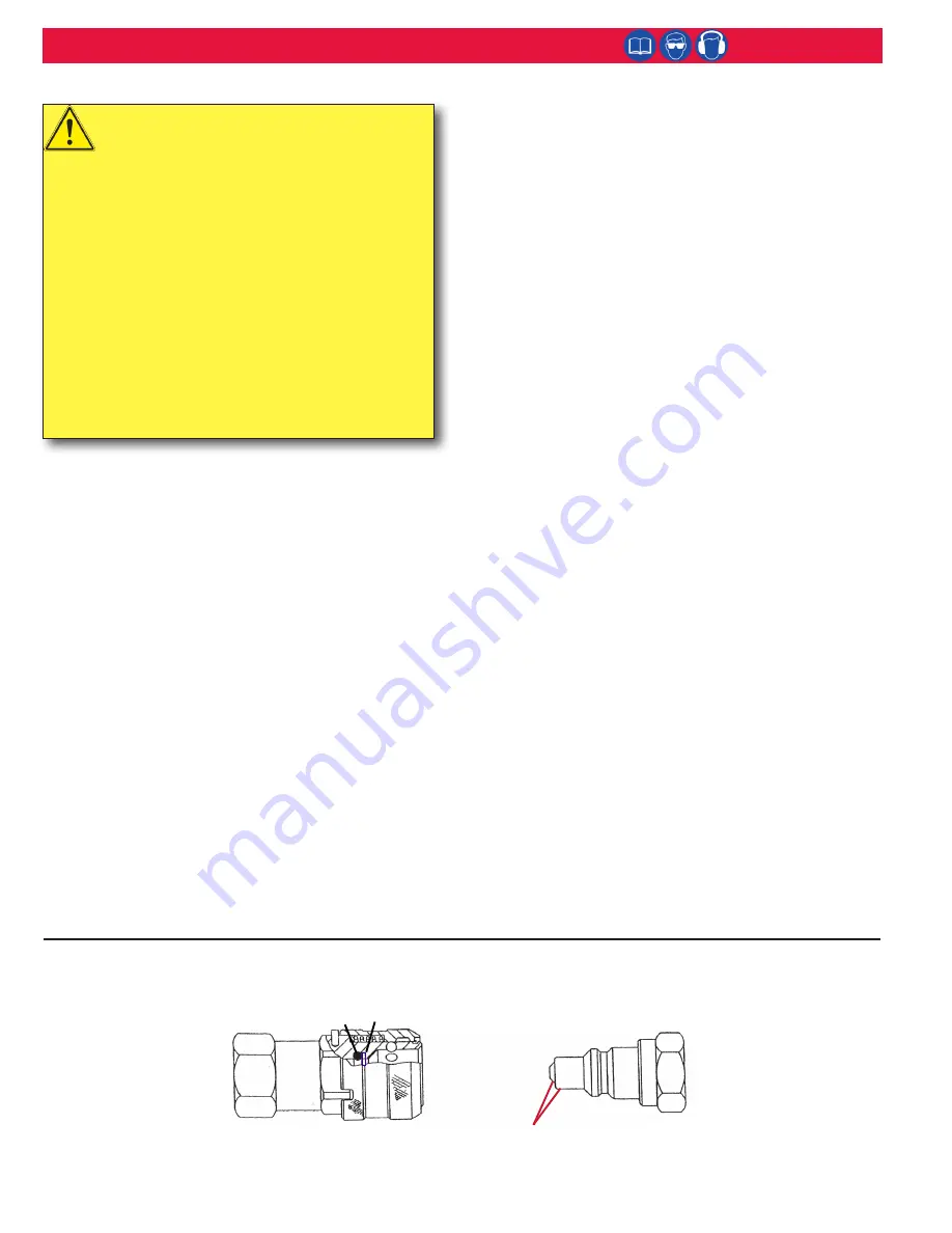
Hydraulic Couplings
504438 O-ring
501102 Back-up Ring
110439
Female
Connector
110438
Male
Connector
Use a fine India stone to remove any nicks or burrs from these
areas to prevent damage to O-ring of Female Connector.
Summary of Contents for 2580
Page 2: ...2 2580 series Hydraulic Installation Tools HK961 ...
Page 7: ...7 2580 series Hydraulic Installation Tools HK961 Assembly Drawing Main Components Figure 2 ...
Page 15: ...15 2580 series Hydraulic Installation Tools HK961 Control Cord Hose Assembly 2580 Figure 5a ...
Page 16: ...16 2580 series Hydraulic Installation Tools HK961 Sectional View A2580 Figure 5b ...
Page 18: ...18 2580 series Hydraulic Installation Tools HK961 Assembly Drawing 2580 Figure 6 ...
Page 19: ...19 2580 series Hydraulic Installation Tools HK961 Assembly Drawing A2580 Figure 7 ...
Page 20: ...20 2580 series Hydraulic Installation Tools HK961 Assembly Drawing 2580 12 Figure 8 ...
Page 21: ...21 2580 series Hydraulic Installation Tools HK961 Assembly Drawing 2580 25 Figure 9 ...
Page 22: ...22 2580 series Hydraulic Installation Tools HK961 Assembly Drawing 2580 38 Figure 10 ...


