Service Support Spirit
Unique Solution
WWW.ARCBRO.COM
86
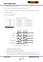
10.3 G Code Explanation
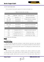
The G code which this system supports for is shown as the table 10.2.
Table 10.2 Common G code table
G99
Parameter: X/U Y/V I J
Part option parameter
G92
Parameter: X Y
Reference point setting
G91 / G90
No parameter
Relative/Absolute coordinate
G20 / G21
No parameter
Inches/metric
G41 / G42
No parameter
Left/right Kerf compensation
G40
No parameter
Cancel Kerf compensation
G00
Parameter: X/U Y/V
straight line rapid moving tool
G01
Parameter: X/U Y/V
Straight line cutting
G02
Parameter: X/U Y/V I J
Clockwise arc cutting
G03
Parameter: X/U Y/V I J
Anticlockwise arc cutting
1.
G92 Reference point setting
Format:
G92 [Xn] [Yn]
Parameters meaning:
[Xn] [Yn] expresses absolute coordinate of setted reference point and is also absolute
coordinate of which machine tool goes back to. If no parameter after G92, the default reference
point coordinate is (0, 0). Generally, while machine tool is taking (0,0) as reference point, this
code can be ignored.
Note:
After input this code, coordinate of reference point setted by G92 can be saved
automatically. Before new cutting code hasn’t been inputted, the coordinate of this reference
point is always available, whether system is power off or not. After input a new cutting code, if


