background image

AVP700

E-8

AVP700

E-9

E

n

g

li

s

h

SCART RGB 4-WIRE CONNECTION

(SCART refers to the multi-pole A/V connector used commonly on European A/V equipment.)
Some video projectors and most European TV sets require the use of a 4-wire RGB connection, where 
the ‘sync’ signal is separate from RGB. In this case, you need to use the composite video 

MONITOR 

OUT


dn

 for the sync information. A cable is available from your dealer to make this 4-wire RGB 

connection (refer to the table of SCART connections at the back of the manual). Note that use of this 
feature requires (in addition to the RGB connections) a composite video connection between the source 
and the AVP700, in order to supply the additional synchronisation signal.
Note that most SCART TV inputs will require the SCART RGB status line to be controlled before the RGB 
signal will be displayed. The RGB trigger output will control this signal when connected to the SCART 
socket using a cable of the type given on page 32. These cables are available from your dealer.
The AVP700 does not support either 5-wire RGB HV or 3-wire RGB sync-on-green connections.

HDMI

An HDMI connection between a source and your display device offers the best possible picture quality. 
This connection type is, however, the most limiting in terms of routing and conversion.
The AVP700 provides two HDMI inputs; these are labelled ‘DVD’ and ‘SAT’ in anticipation of the 
most common use for these connectors, but they may be used for any HDMI source. These inputs 
may be confi gured to be associated with any of the other sources, so that selecting that source 
(‘AUX’, for example), selects one of the HDMI inputs instead of the usual input associated with 
that source.
It is important to realise that analogue video sources cannot be routed by the AVP700 to the HDMI 
output, nor can either of the HDMI inputs be converted to analogue video (of any sort). The AVP700 acts 
simply as a switching device, selecting one of the inputs and routing it to the output.
Keeping the above in mind, it will be necessary (as with the high-quality analogue video connections), 
to provide a composite video feed, in addition to the HDMI connection, if the video is to be routed to 
Zone 2.

Zone 2 connections

The AVP700 allows independent routing and control of analogue audio and composite 
video to a second room such as a kitchen, bedroom or lounge. This second room is known 
as ‘Zone 2’.
For Zone 2, the AVP700 outputs a line-level audio signal taken from the stereo analogue 
audio, and a composite video signal taken from the composite video input (for a given 
source). The analogue inputs are required because there is no analogue-to-digital, DSP 
processing or digital-to-analogue conversion available for Zone 2 signals. As the AVP700 
does not convert video formats for Zone 2, a composite video signal must also be 
connected from the source. 
For these reasons, we recommend that source devices that have a digital connection are 
also connected via the analogue inputs. High quality YUV/RGB and S-video sources should 
also have their composite video outputs connected to the AVP700 for use in Zone 2.

NOTE:

 As a composite input is required for Zone 2, it may not be 

possible to run your DVD player in progressive scan mode and to use 
Zone 2 at the same time, unless your DVD player can output both 
progressive scan and composite signals simultaneously.
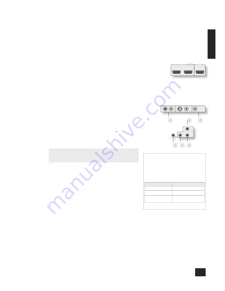
eq


ZONE 2 OUT

.

This is the audio output for Zone 2. Connect these to a line level input on 
your Zone 2 amplifi er.

do


ZONE 2 VIDEO OUT

 (Composite video connection). 

This is the video output for Zone 2. Connect to your Zone 2 video display 
using 75Ω low loss coaxial cable.

fk


IN ZONE 2

This allows the AVP700 to be controlled remotely from Zone 2 via infrared 
remote control. See the panel for connection information.

MON

OUT

ZONE2

VIDEO

OUT

ZONE

2

��

��

REMOTE

IN

ZONE

2

IN

LOCAL

OUT

12V

TRIGGER

(Z1 & Z2)

��

�� �� ��

Zone 2 remote controller connection.
A receiver compatible with this connector 

fk

 is 

available from Xantech (part no. 291-10). Please 
contact a Xantech registered dealer for this part, 
as ARCAM does not stock them. 
See 

www.xantech.com

 for more information.

The 3.5mm jack plug for this connector is wired 
as follows:

3.5mm stereo jack

Function

Tip

Signal

Ring

0V

Sleeve

12V,
30mA current-limited

This follows the Xantech standard for IR 
transmission over wire.

HDMI

DVD

SAT

OUT

IN

Summary of Contents for AVP700

Page 1: ...OK MANUEL HANDBUCH HANDLEIDING Arcam AVP700 Pre amp processor Pr amplificateur processor Arcam AVP700 Vorverst rker Prozessor Arcam AVP700 Arcam AVP700 Voorversterker processor English Fran ais Deutsc...

Page 2: ...ucing equipment such as radiators stoves or other appliances including other amplifiers that produce heat 6 Climate The appliance has been designed for use in moderate climates 7 Racks and stands Only...

Page 3: ...nd modes E 25 Introduction E 25 Digital multi channel sources E 25 Two channel source modes E 26 Multi channel source modes E 26 DSP Effects Modes E 27 Speaker positioning E 27 Troubleshooting E 28 IR...

Page 4: ...page 3 should help you find the sections of interest Safety Safety guidelines are set out on page 2 of this handbook Many of these items are common sense precautions but for your own safety and to ens...

Page 5: ...itionally to provide analogue audio and video connections as described above Zone 2 A line level signal from the stereo analogue audio together with the composite video inputs are available for Zone 2...

Page 6: ...the use of high quality screened analogue digital and video cables since inferior quality cables will degrade the overall quality of your system Use only cables that are designed for the particular a...

Page 7: ...TS cl CD cm DVD cn AV co SAT cp AUX cq TAPE Connect the digital outputs of your available source equipment to these inputs If required each of these six inputs can be allocated to a different audio in...

Page 8: ...site video outputs to the video input of your VCR or AUX The connection used must match the video type of the source you wish to record as described above For example if you wish to record a S video s...

Page 9: ...ections to provide a composite video feed in addition to the HDMI connection if the video is to be routed to Zone 2 Zone 2 connections The AVP700 allows independent routing and control of analogue aud...

Page 10: ...to be controlled via the 3 5mm IR jack socket Arcam units only or by using an IR emitter stuck to the centre of the IR sensor window on the source component such as a Xantech 283MW mini emitter et IN...

Page 11: ...Pressing the menu button for just a short time will take you to Main Menu Screen 1 If this happens the Main Menu can be closed by pressing MENU for a second time 2 When the menu heading is highlighte...

Page 12: ...SCRN CTRL Composite This mode is used to indicate to your TV that composite video is being sent It uses the trigger labelled 1 RGB fl which should be connected to the RGB SCART input on your TV as sho...

Page 13: ...bass redirection begins Frequencies below this level are redirected from small speakers to the Fronts or to the sub woofer frequencies above this level are not redirected The value for this setting de...

Page 14: ...utputs of an Arcam DVD A player then this item should be set to 10dB 4 Speaker Delay Settings The relative positioning of speakers within a room may mean that sound from some speakers arrives at the l...

Page 15: ...dB The output from each speaker needs to be adjusted to the 75dB SPL sound level No adjustments can be made for a speaker that is not selected in the previous Speaker Sizes menu Note that inserting he...

Page 16: ...d video assigned to track each other by default The five Video Input lines for Tape CD FM AM and DVD A allow assignment of a video source to these normally audio only sources If desired it is possible...

Page 17: ...ress again to enable the source Enabled sources are listed on the Access line of the menu page ADV 5 Analogue Settings Input trims Allows the adjustment of the input sensitivity of the analogue inputs...

Page 18: ...AMP button first to operate the AVP700 On Stand by This allows the AVP700 to be put into and taken out of stand by remotely Navigation buttons Arrow buttons allow navigation around the menus on the A...

Page 19: ...he volume control knob The volume level is shown on the display Note that different sources may require different settings of the volume control to achieve the same perceived volume level It is import...

Page 20: ...ly These are configured to allow recording of the source that you are watching Pressing the VCR or AUX button selects audio and video from the VCR AUX input The VCR AUX LED will illuminate together wi...

Page 21: ...in Speaker Eq is still 6dB not 12dB To select the speaker to be adjusted press the Treble Bass button repeatedly until the desired speaker is shown on the front panel display Then use the volume cont...

Page 22: ...e the preset is stored the display reverts to show the station name if RDS information is transmitted or its frequency To quit the memory function without storing a preset leave the tuner controls unt...

Page 23: ...the front panel or the remote Changing the video input does not change the audio input so you can watch a different input from the one you are listening to If the audio and video are set to different...

Page 24: ...akers to create a phantom centre image The Centre Width control allows variable adjustment of the centre image so it may be heard only from the centre speaker only from the left right speakers as a ph...

Page 25: ...remember this for all bitstream sources e g DTS ES Matrix Dolby Digital 3 0 etc and use the maximum number of speakers the signal is encoded for As a result when a 2 0 or 2 1 bitstream is played the...

Page 26: ...stereo sources can sound muffled and compressed DTS NEO 6 DTS Neo 6 provides up to six full band channels of decoding from stereo material The AVP700 will derive separate channels corresponding to th...

Page 27: ...urround left surround right left surround back right surround back and an active sub woofer see diagram All speakers with the exception of the sub woofer should be arranged around your normal viewing...

Page 28: ...problem occurs when using an HDMI connection try using a shorter cable In general HDMI signals cannot be run over such long cables as analogue signals There is no On Screen Display OSD Is your video d...

Page 29: ...has been found Try re arranging cabling from the suspect source away from other cabling and ensure that the cabling used is high quality specified for its purpose and properly screened If the problem...

Page 30: ...nd Command code Command Command code Stand by 124 MODE 32 On 123 Mono mode 106 Zone 1 stand by 125 Stereo mode 107 Power toggle 12 Dolby PLII Movie 108 Display DIS 59 Dolby PLII Music 109 Menu MENU 82...

Page 31: ...3 if pressed for 1 second 5 Command Command code Preset 6 preset 14 if pressed for 1 second 6 Preset 7 preset 15 if pressed for 1 second 7 Preset 8 preset 16 if pressed for 1 second 8 Preset 9 9 Prese...

Page 32: ...7 Sleeve Coaxial cable 6 and 7 18 Ground RGB switching control Stereo Mini Jack 3 5mm Sleeve Screened cable 19 Video output composite RCA Phono 6 Centre Coaxial cable 6 Comp out 20 Video input compos...

Page 33: ...ge level excl RGB status 12V 1V Allowable load 30mA max min 400 Remote inputs and output Signal modulated 36kHz carrier Coding Philips RC 5 General Mains voltage 110V and 230V switchable Power consump...

Page 34: ...portation costs at any time Claims under guarantee This equipment should be packed in the original packing and returned to the dealer from whom it was purchased or failing this directly to the Arcam d...

Page 35: ...code the parameters for the reponse ETR End transmission 0xd The AVP700 responds to each command from the RC within three seconds The RC may send further commands before a previous command response h...

Page 36: ...n the Set up menu is lost f Ouvrez l un des menus du syst me AVP700 Si le menu Set up est ferm en raison de l ouverture d un autre menu toute modification apport e au menu Set up est perdue d Aufrufen...

Page 37: ...ermer le menu Main d Befehls R ckmeldesequenz zum Schlie en des Hauptmen s n Opdracht en responsreeks om het hoofdmenu te sluiten Com PC_ 11 followed by suivie d un gefolgt von gevolgd door 0xd Resp A...

Page 38: ...mmand response sequence to decrment the volume by 1dB in Zone 2 where the resulting volume is 56dB f S quence commande r ponse pour baisser le volume de la zone 2 de 1 dB o le volume obtenu est 56 dB...

Page 39: ...0x30 van de gerapporteerde waarde aftrekken Formule feitelijk volume gerapporteerd volume 0x30 De opdracht kan hierdoor waarden vereisen retourneren die niet in ASCII tekens omgezet kunnen worden geb...

Page 40: ...de de d codage pour le mat riau multicanal d Einstellen des Dekodiermodus auf Mehrkanalmaterial n De decoderingsmodus voor meerkanaals materiaal instellen Example Exemple Beispiel Voorbeeld g Command...

Page 41: ...hls R ckmeldesequenz zur nderung der Audioquelle in digital n Opdracht en responsreeks om de geluidsingang naar digital te wijzigen Com PC_711 followed by suivie d un gefolgt von gevolgd door 0xd Resp...

Page 42: ...preset 0x30 f Augmentation diminution de la pr s lection actuelle du tuner La valeur retransmise pour la nouvelle pr s lection est d cal e de 0x30 Pour obtenir la valeur correcte tez 0x30 de la valeu...

Page 43: ...g Command response sequence to increment the FM tuning from 85 0MHz to 85 05MHz f S quence commande r ponse pour incr menter le r glage FM de 85 0 MHz 85 05 MHz d Befehls R ckmeldesequenz zur Erh hung...

Reviews: