background image

5

OPERATING
TECHNIQUES

Cutting Without Power

This is the most commonly used
method of cutting with this type of
equipment.  To cut without power
connect the torch to either terminal of
a 12-volt battery or constant-current
welding power source.  Connect the
striker or a strike plate to the other
terminal.  If using a welding power
source, set output level for 100 amps.
Turn on the oxygen supply and adjust
the regulator to the proper working
pressure.  Insert the cutting rod into
the collet and tighten the collet ring.

Tap the cutting rod on a hard,
ungrounded surface to seat the rod in
the torch.  Depress the torch oxygen-
valve lever and check for oxygen
leaks around the collet ring.  If
oxygen is leaking, repeat the
procedure until no oxygen is leaking.

Put the torch in one hand and striker
in the other.  Depress the oxygen
lever and touch the cutting rod to the
striker.  As soon as the rod is ignited,
remove the striker. Move the burning
rod to the workpiece and begin
cutting.  The cutting rod should be
held at a 45

°

 to 80

°

 drag angle from

the workpiece surface.  This angle
depends on the thickness and type of
material being cut. (See Section
"Important Process Variables",
Paragraph  "Electrode-to-Work
Angle")

As the cut progresses, slight contact
should be made between the burning
rod tip and the workpiece.  This
placement requires two motions: first,
inward towards the workpiece as the
rod is consumed, and second, in the
direction of the cut.  Since there is no
electrical arc when cutting without

power, wear at least a #5 shade lens
for eye protection.

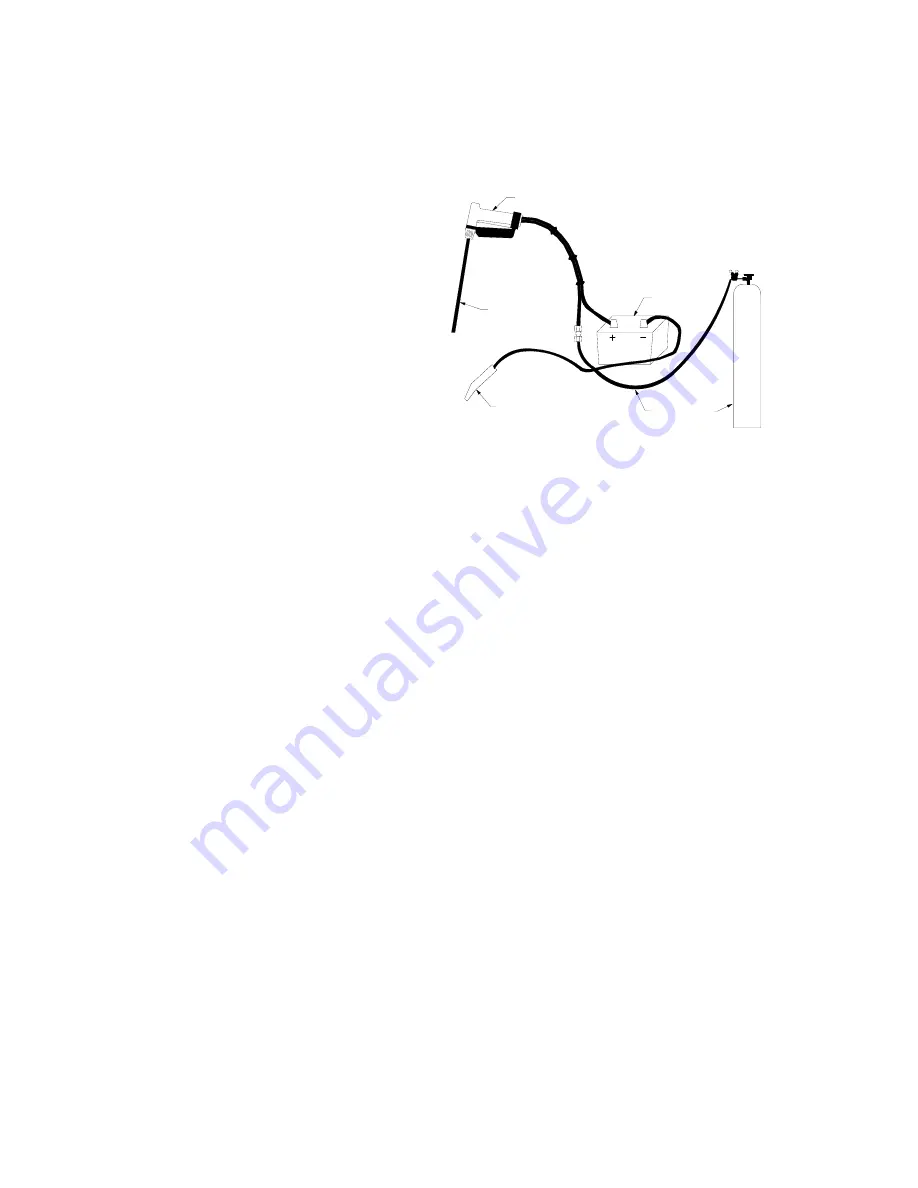
FIGURE 2 Cutting Without Power

Cutting With Power

Cutting with power or an electric arc
is done by connecting the torch to
one terminal and connecting a
welding ground clamp to the other
terminal of a CC welding power
source.  The ground clamp is then
attached to the workpiece.  Unlike
other processes, this process can use
a welding power source set for DCEP
(reverse polarity) or DCEN (straight
polarity).  AC (alternating current)
power supplies can also be used
without affecting cutting performance.
Don't cut with power using a
constant-potential power source.

Insert the cutting rod into the collet
and tighten.  Start the oxygen flow,
touch the rod tip to the workpiece,
and begin cutting.  Again, as in
cutting without power, the cutting rod
should be held at a 45

°

 to 80

°

 drag

angle from the workpiece surface.
(See Section "Important Process
Variables", Paragraph "Electrode-to-
Work Angle")  As the cut proceeds,
make slight contact between the
burning rod and the workpiece.  This
placement requires two motions: first,
inward towards the workpiece as the
rod is consumed and, second, in the

12 VOLT BATTERY

(IGNITION SOURCE)

TORCH

STRIKER

CUTTING ROD

OXYGEN SUPPLY

1. CONNECT TORCH TO NEGATIVE LUG ON BATTERY.
2. CONNECT STRIKER TO POSITIVE LUG ON BATTERY.
3. SET OXYGEN PRESSURE TO 80 PSI.

4. TIGHTEN CUTTING ROD IN TORCH COLLET.

5. DEPRESS OXYGEN TRIGGER ON TORCH.

6. TOUCH CUTTING ROD TO STRIKER TO IGNITE ROD.

Summary of Contents for SLICE

Page 1: ...1 Instruction Manual For SLICE Exothermic Cutting Equipment...

Page 2: ...forced through the lance and the third the heat of combustion some external source of heat However when the lance pierces a slag puddle the puddle becomes the source of heat until the lance is withdra...

Page 3: ...ork piece to achieve the most efficient cut Rods used in exothermic cutting can be consumed without any cutting taking place Tip contact tells the operator that the most intense heat from the rod is i...

Page 4: ...sed air could cause serious injury to the operator The torch could burn from the inside or even explode from the buildup of dirt from the compressed air in the oxygen supply tube Cutting Rods SLICE Cu...

Page 5: ...workpiece as the rod is consumed and second in the direction of the cut Since there is no electrical arc when cutting without power wear at least a 5 shade lens for eye protection FIGURE 2 Cutting Wit...

Page 6: ...e flat position is more difficult than piercing horizontally Progression while piercing flat will also be slower Example Piercing a hole in a floor is more difficult and slower than piercing a hole in...

Page 7: ...ent he needs to compliment his shop or service vehicle These packs start with the very basic unit that includes torch striker and other support items in a handy toolbox This type pack is just right fo...

Page 8: ...psi is advantageous for scarfing Lower pressures offer a more controllable scarfing action With material thicker than 3 pressures over 80 psi can be used to give the oxygen enough velocity to blow awa...

Page 9: ...gen to produce its very effective cuts Industrial standards associated with oxygen use electrical equipment cutting procedures and other safety precautions apply when using this equipment This section...

Page 10: ...welding power supply Whenever possible do not use electrical power to do exothermic cutting SEE SAFETY AND OPERATING REFERENCES 1 AND 2 SMOKE FUMES AND GASES CAN BE DANGEROUS TO YOUR HEALTH Keep smok...

Page 11: ...Do not cut containers that have held combustibles All hollow spaces cavities and containers should be vented prior to cutting to permit the escape of air or gases Purging with inert gas is recommende...

Page 12: ...ems Punch lag holes to secure machinery Repair machine bases Remove old machinery Cut up or repair storage tanks Heavy Equipment Maintenance General maintenance field or shop repairs Repair buckets Re...

Page 13: ...on Solution 1 To much gap between the burning rod tip and the workpiece Must maintain slight pressure against workpiece 2 Travel speed too slow 3 Oxygen pressure too low Problem Molten material not be...

Page 14: ...te the listed type that most resembles the material to be cut NOTE All these cutting values are based on 1 4 diameter flux coated rods Cutting rates with 1 4 bare rods will be slightly less than the v...

Page 15: ...onds 42 049 003 1 4 22 Coated 100 80 7 5 CFM 40 45 Seconds 43 049 002 1 4 22 Uncoated 25 80 7 5 CFM 40 45 Seconds 43 049 003 1 4 22 Uncoated 100 80 7 5 CFM 40 45 Seconds 43 049 005 1 4 44 Uncoated 25...

Page 16: ...319 11 6 Extension 94 168 023 12 Extension Shield 94 777 111 Striker NS Striker Handle Kit 94 370 181 NS Striker Bar 96 070 031 NS Striker Cable 96 130 320 SLICE Accessories Description Part Number D...

Page 17: ...76 021 72 012 007 96 076 021 Torch Extension 94 168 023 94 168 023 94 168 023 94 168 023 94 168 023 Extension Shield 94 777 111 94 777 111 94 777 111 94 777 111 94 777 111 Red Battery Clamp 96 168 035...

Page 18: ...162 752 4 Battery Assembly 96 076 018 5 6 Pin Male Connector 96 169 382 6 Red Female Panel Receptacle 96 169 374 7 Black Female Panel Receptacle 96 169 375 8 Meter 96 508 041 9 Toggle Switch 96 834 3...

Page 19: ......

Page 20: ...e 300 16052 Swingley Ridge Road St Louis MO 63017 636 728 3000 THERMADYNE U S CUSTOMER Service P O BOX12250 Wichita KS 67277 800 231 9353 FAX 800 633 9513 Form No 89 250 845 07 2003 Tweco Products Inc...

Reviews: